Update: PWM pump regulation draws only 1.25a at idle đź‘Ť (Full 43psi)

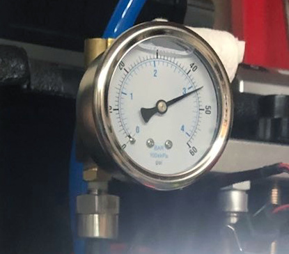
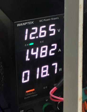
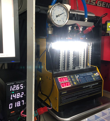
Well this worked even better than I’d anticipated. Turns out that NanoEFI’s method of PWM fuel regulation only requires around 1.25a at idle to maintain 43psi at the injector :astonished:

This resolves a long-standing question about how much electrical power the system requires, and is great news for engines with limited charging output, without needing expensive stator upgrades in many cases.
image

image

The 1.48a reading includes both the NanoEFI ECU and the main relay, both draw approximately 125ma each. So 1.48a total, minus 0.125a (ECU), minus 0.125a (Relay) = ~1.23a pump draw :exclamation:

This same fuel pump is rated to draw 5a @ 43psi when used with a traditional regulator (running full blast all the time).

After theorizing the PWM for a while, it’s good to finally have it tested and known.

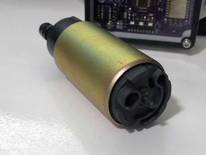
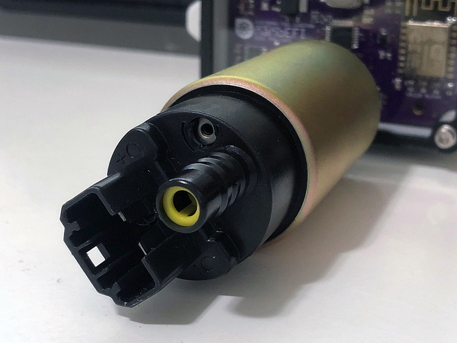
To clarify, this isn’t a expensive special pump like we’re used to seeing on other small engine kits. It’s a mass-produced standard automotive fuel pump (regular turbine style) you can grab off Amazon for $15 and fits hundreds of existing injection cars, motorcycles, ATV’s, etc. They’re absolutely everywhere.

If you’re not familiar with PWM fuel regulation, it’s a way of controlling the speed of a pump’s DC motor, ultimately reducing the electrical energy required to pump fuel up to injection pressures (43psi usually). NanoEFI is able to reduce the speed of the fuel pump. Slowing it down by limiting its current, rather than its voltage.

It also has the benefit of being a returnless system, meaning you won’t need to drill into your fuel tank or run an extra line.

The next challenge will be to convert this style of in-tank pump to work outside of the tank. Normally in-tank pumps take advantage of the surrounding fuel for cooling. However, I’m not anticipating thermal issues thanks to the reduced current with PWM. What I’m more concerned about is sealing the input in a ruggized way that is able to handle bumps and scrapes outside of the tank.
3 Likes

9 posts were split to a new topic: Kit fuel pump?

Pretty cool, but I still say there is merit in over engineering the fuel system for a bypass regulating/polishing approach if the power is available. I’m curious what kind of pressure sensor you are using and its cost?

Modulated regulation is superior. But what’s most important is that the capability is there for both options.

I’ll likely only recommend a traditional passive regulator w/ return line on builds that require using both of the ECU’s high current channels for two separate injectors (E.g. dual cylinder sequential arrangements).

If it’s a single cylinder engine build, just let the ECU actively manage fuel regulation for you. You’ll love it. So will your battery and stator :heart:

Any 5v (0.5-4.5v) ratiometric pressure sensor will work with the ECU as long as it’s chemically compatible with the fuel you’re running. I’m using a 316 stainless steel sensor in the $10 - $15 price range.

1 Like

Have you tried simulating the following:
Beginning conditions:

  • Fuel pressure = 0.00psi
  • Engine = off (& cold for that matter)
  • no battery type bike (e.g. a pit bike)

Then simulate kick/pull starts to see if the stator puts out enough power to boot up the nanoefi AND prime the fuel system. Would it be worth it to add a logic rule that sets a min fuel pressure before injectors “fire”? I imagine you don’t want dribbles of fuel that could “flood” an engine in the typical carburetor sense.

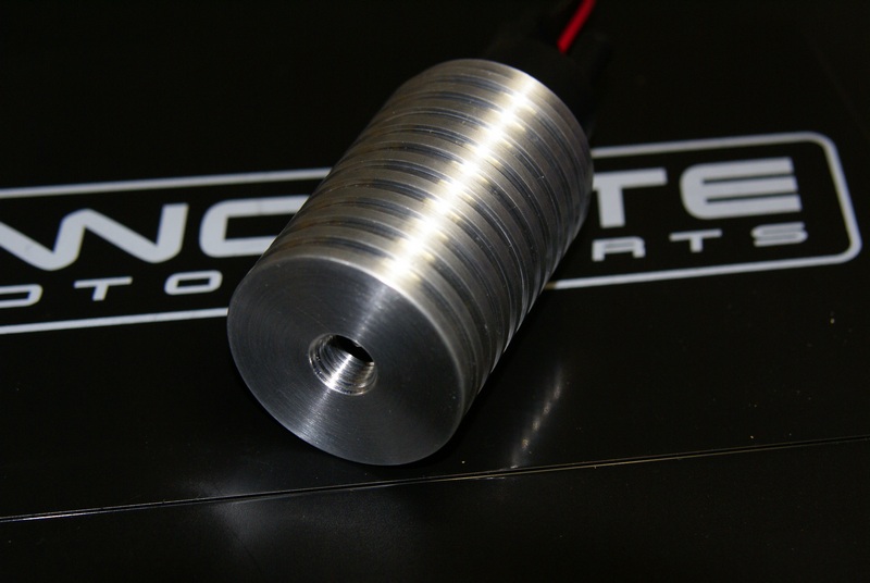
Wow that’s great Travis. The current limit was an issue for my first FI project as the machine I’m working with (Suzuki DR650) only has a 200 watt stator. I tried using a Toyota in tank fuel pump with my own machined finned aluminum housing for cooling but the current draw was prohibitive for my machine. Ended up with a stock external fuel pump for a Suzuki LT450R (FI’d ATV) which had a very reasonable current draw similar to what your PWM system is drawing.

Hi @cwirtz703 and welcome! Thank you for your support!!

Good question. Batteryless injection has come up a few times. Although I haven’t tested this use case, what I can say for sure is that the ECU very quick to boot, setup and get right to it’s main loop. As long as your stator and rectifier/regulator can establish a stable output of at least 9 or 10v DC for at least three crank revolutions (if using a single-point trigger), I don’t see the ECU itself having a problem with kick starting and no battery.

I think that’s going to depend model to model. I can’t say for sure at this point, although I won’t rule it out especially for stronger three-phase stator and rectifier systems. If you’re on a single-phase setup though, (especially with half-wave output) I don’t see that working. I’ve heard of “battery eliminator” capacitors that may help, but I have no experience with them at this point. Might be less headache in the end to just throw on a small 4aH battery or something like that.

You may be right, one line will take care of that. I’ll add the minimum pressure setting, and if we run into a reason that might actually be beneficial to allow dribbles as a last resort to try to get something started we’ll take another look at it.

Thanks, and nice machine work!

You read my mind, I believe capping the suction side like you’ve done is the way to go. Combined with PWM control I think we’ll have a winner.

At what engine speed is that 200w rating? Idle?

Yes, just off idle. Then it drops a bit. The stator can be rewired from wye to delta for a bit more juice higher up but it obviously affects the lower RPM range which the DR650 tends to spend a good portion of it’s running time in. I changed every bulb on my bike over to LED’s which gave me enough current to run my FI system. Going to a mosfet reg/rect on the DR650 also helps with current savings.

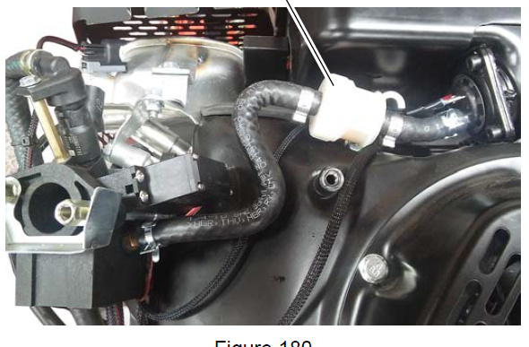
In my recent research I noticed Ariens implemented PWM controlled fuel pressure in their EFI snowblowers. Fuel comes from in-tank (High pressure) pump, to filter, to throttle body unit which contains the pressure sensor… Then back out of the throttle body unit to the injector.

image

I have a separate PWM controller controller along with a big honkin pressure sensor. This seems much more compact.

PWM is pretty common in cars of course, but this is the first time I’ve seen it implemented in a small engine in this manner.