Welcome xs650 project

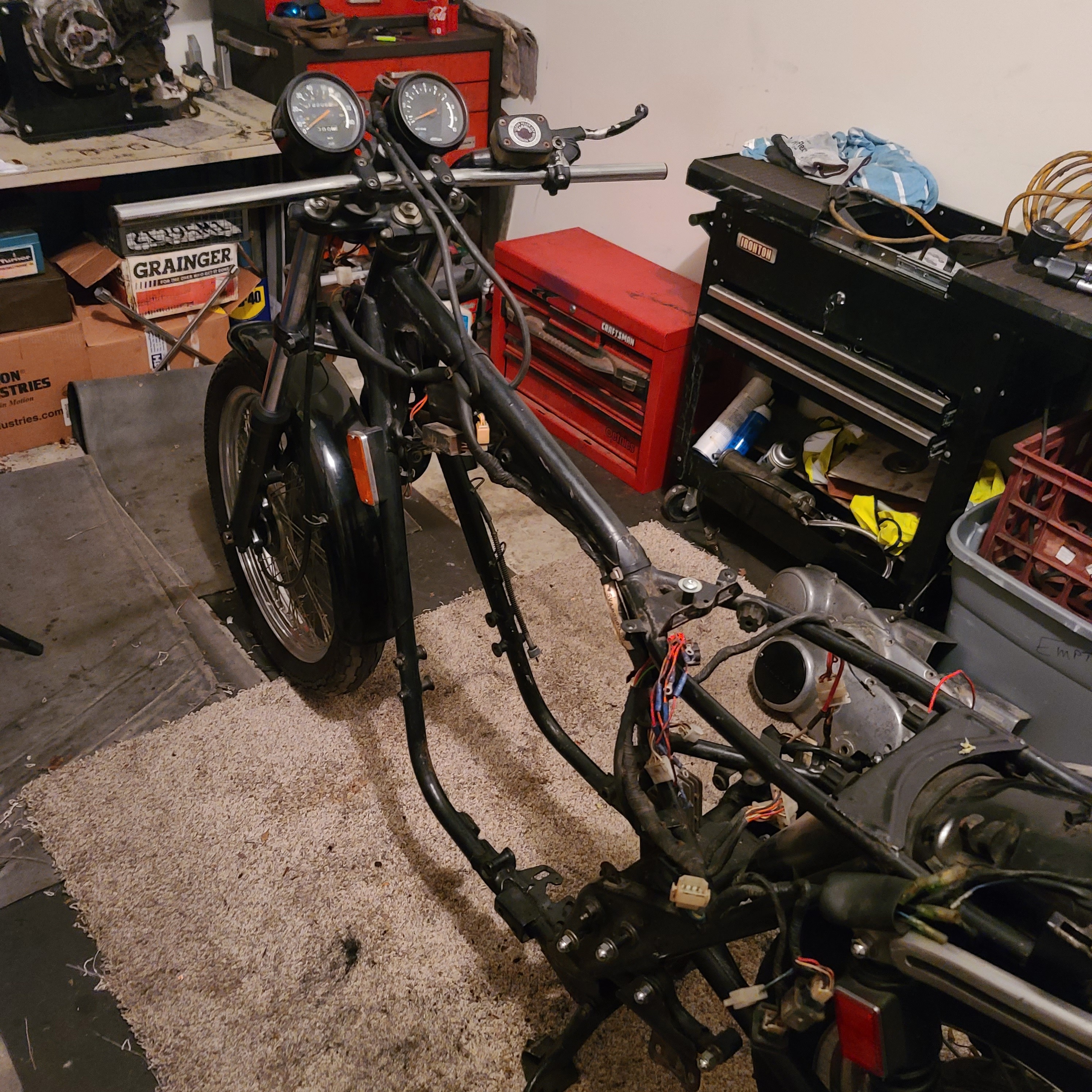
Hello! I have been interested in small engine efi for years and think this is fantastic. I have a 2 stroke twin rd350 and a 4 stroke parallel twin xs650. Both are excellent candidates. The xs650 has 120mm spacing just like an ex600 kawasaki. I can adapt a kawasaki throttle body onto an xs easily. I just need the controller. I was originally going to use mega squirt. But this looks way easier! I would love to help develop this system.

I am an industrial maintenance technician and accomplished electrician and fabricator. I am very interested in seeing how I could help set this up. I am adapting a fully rectified ac to 12v DC system and making my own CDI setup using a zeeltronics controller. I have power and ignition covered. But I would prefer to go efi instead of using pumper carbs.

My plans are as follows.
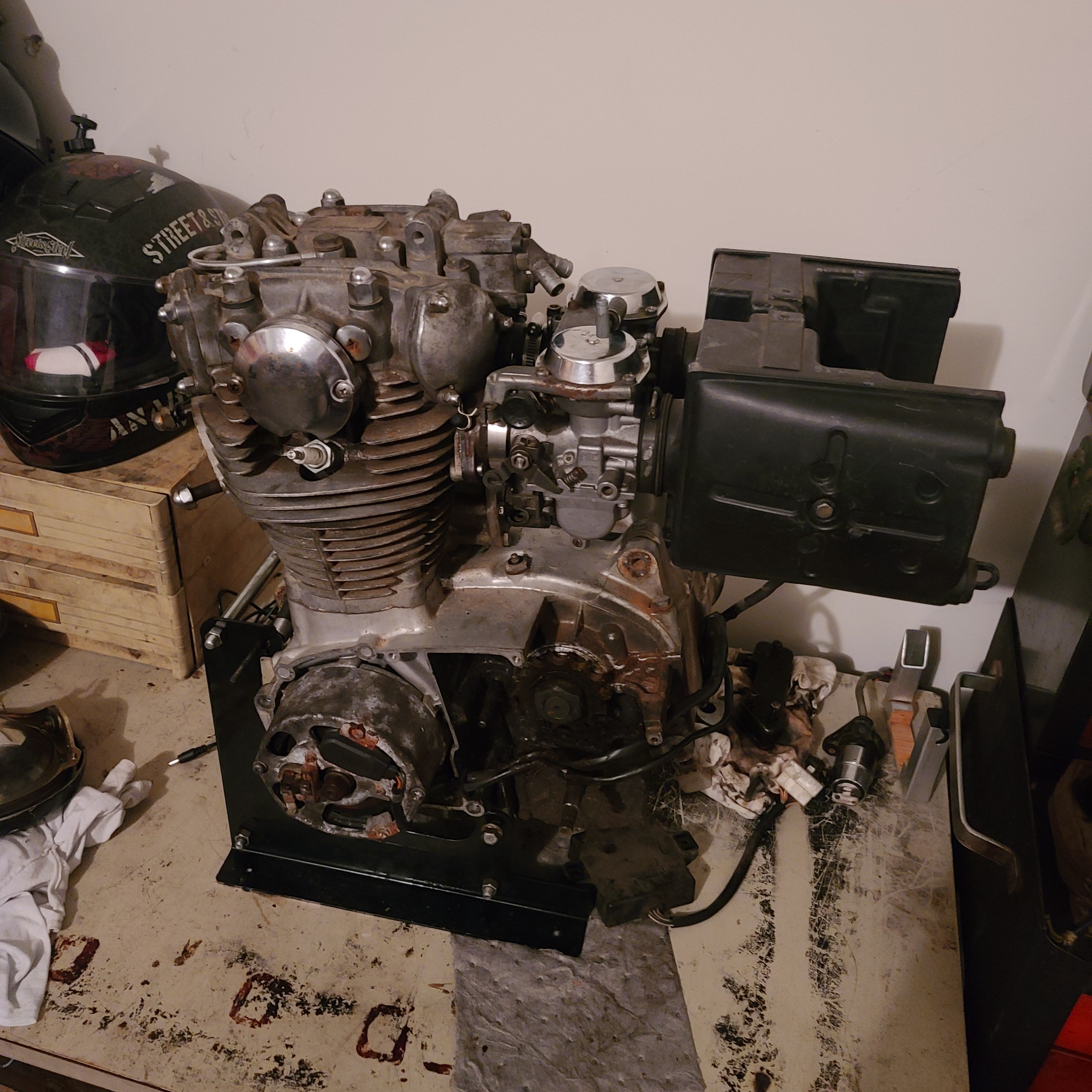
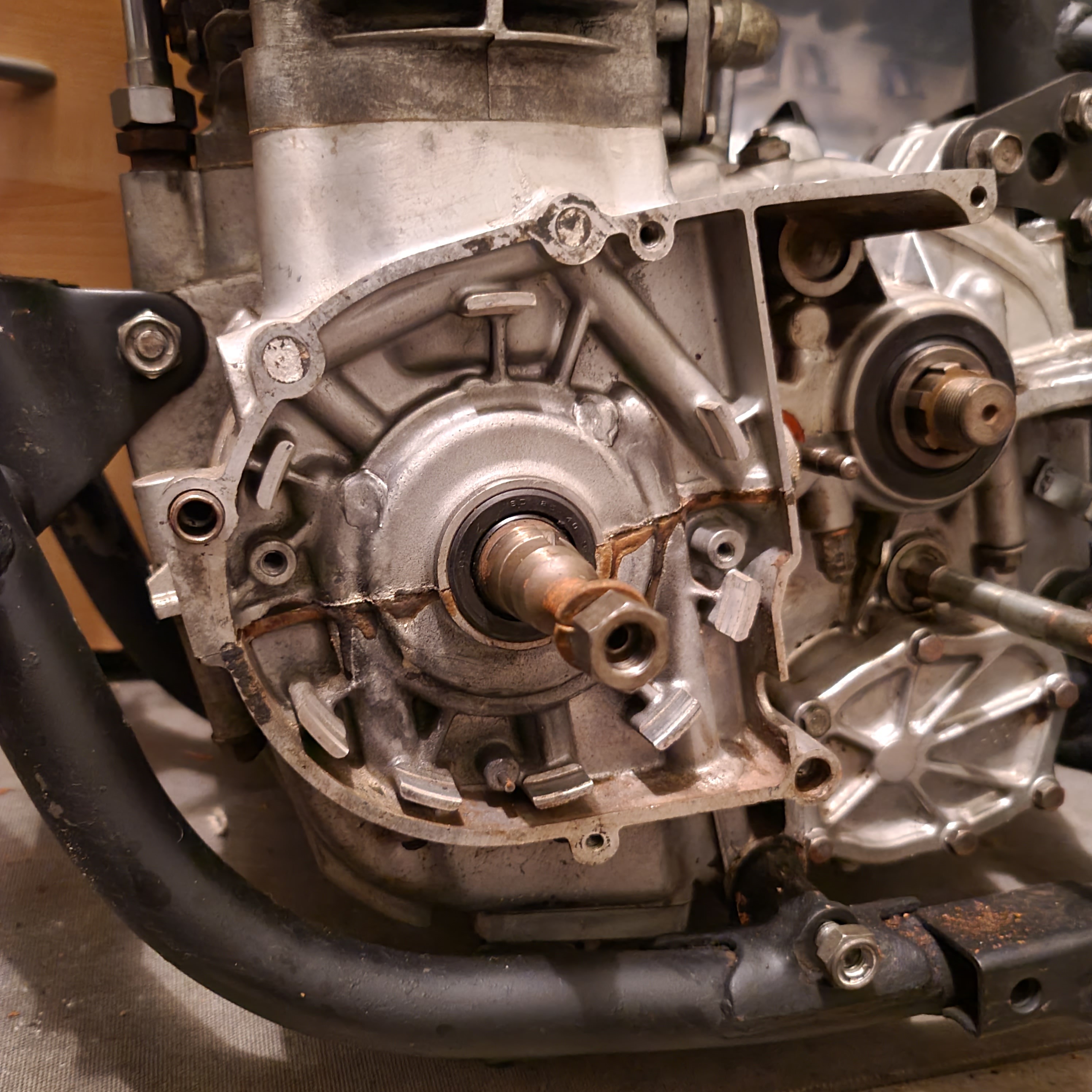
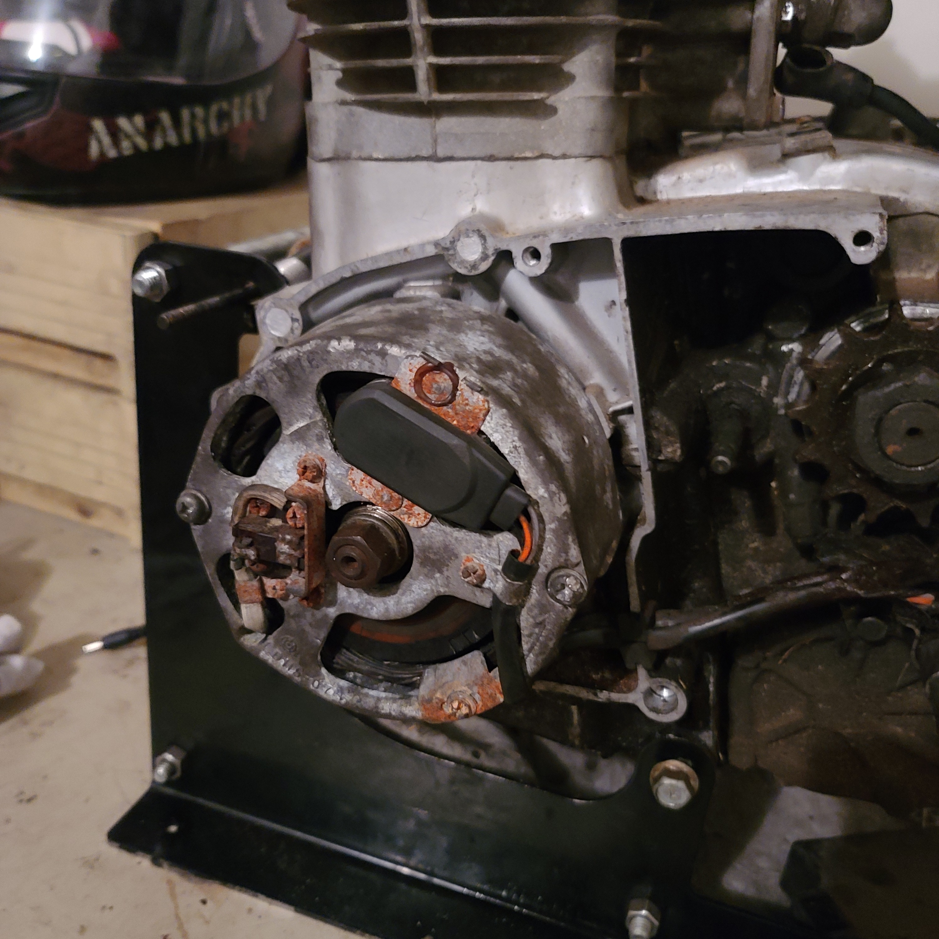
The xs650 is completely analog. nothing digital. It still used an excited field brushed generator.
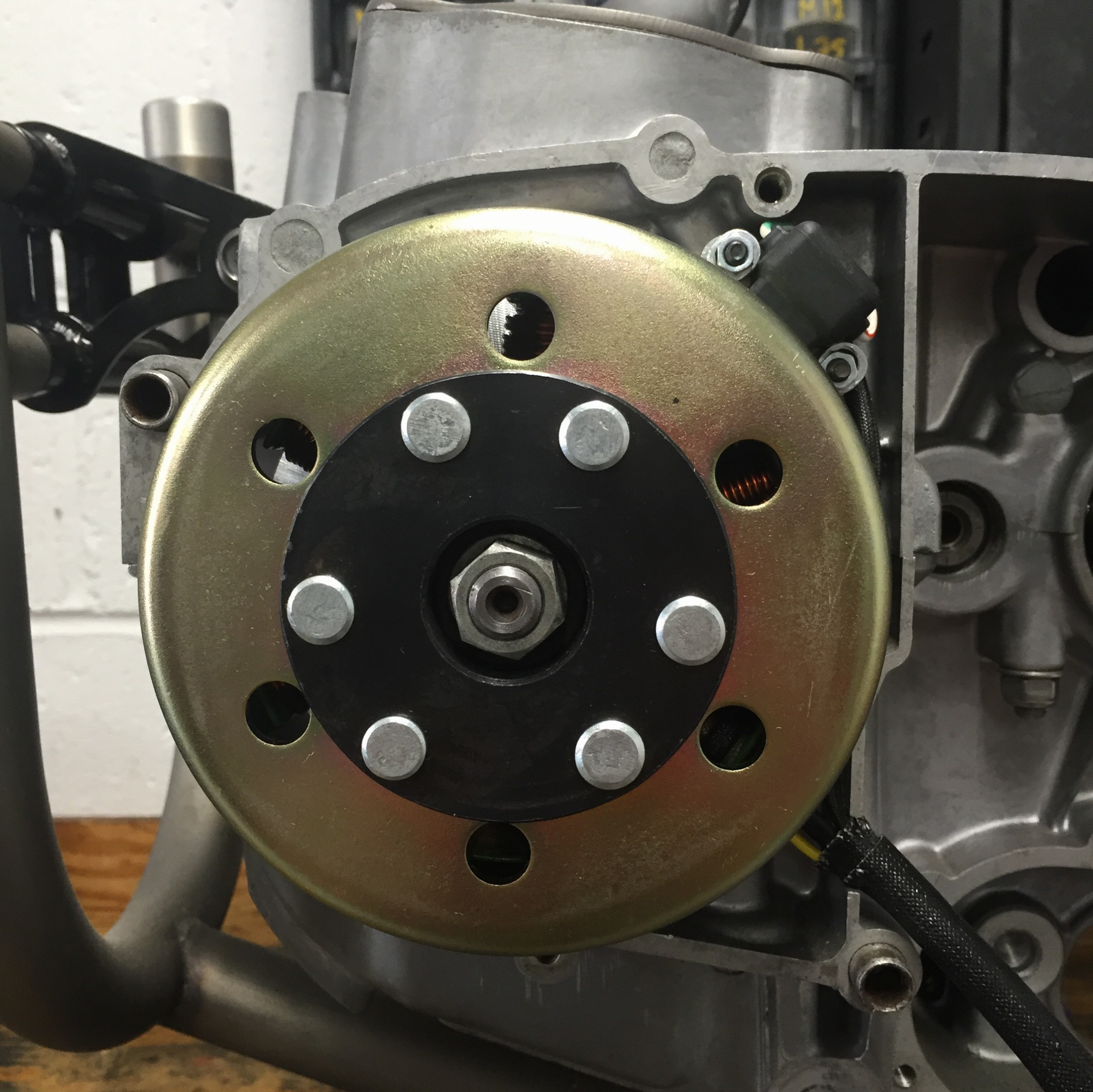
First plan is to convert to Modern 200 watt PMA alternator, in progress.
After I convert the bike to the PMA system I can install your ECU to power the Ignition and fuel requirements. With your Fuel injection controller I can very easily have a motor running off of EFI.

I can use Harley head k type head temp as the CLT sensor. I can use a set of EX500 throttle bodies, they have TPS, IAT, as well as a fuel rail and injectors. That throttle body literally fits right on.
I would use a Harley sportster fuel pump to get to the required fuel pressure. or a provided fuel pump and install a pressure guage in line

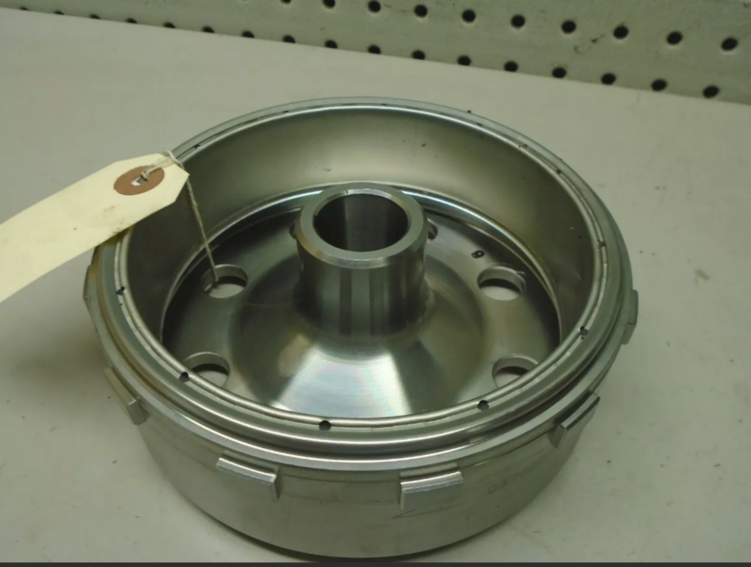
The PMA Rotor or Flywheel is from a Yamaha Banshee quad and after being installed I can create a tone ring, if you needed a high resolution signal to repeat back to the ecu. or use the factory single position pulsar coil.

What else would you need to know?

I also have a Yamaha RD350 aircooled two stroke 350 cc twin that I would think would be extremely promising. It is incredibly popular and I can use the same alternator as on my xs650. Its a race bike and it would be a great test of the true potential and range of the device.

Welcome @Shaggymech! :wave:

If 200w is the goal and fabrication of a crankshaft adapter isn’t an issue, I’d recommend a GY6 11 or 12 pole stator / flywheel / regulator combination for minimal cost.

Single pulse triggering is fine. An encoder ring won’t be needed for most scenarios where the goal is to replace a carburetor and keep your ignition timing reasonable. Most of us want to kick the carb with a focus on reliability.

For performance builds, I have a software-based approach in mind which may help the ECU predict instantaneous crank speed between pulses. Help emulate the precision of a toothed wheel on a single-pulse trigger setup. But at this point I can’t say with certainty. So if you’re looking to push boundaries on a performance build, an encoder ring is probably going to be recommended.

Looks like you have most of the bases covered. Be sure to post pictures of your prep along the way!

The Banshee/Modern stator setup is a bolt on setup that nearly all XS650 do to eliminate the antiquated field excite coil generator. It produces weak spark with the breakers, and when Yamaha went to a Tci ignition in 1980, it is troublesome at best. The Banshee flywheel and stator actually produce nearly 350 watts at 10000 rpm. it will be 200 watts of available power at nominal rpm. say 5000.
Prior to selecting the banshee setup (which is actually an incredibly common swap for yamaha’s in the mid 70’s) I had looked into the gy6 stator but the taper is honestly to small to fit. I would need to machine a #6 taper deeper into the gy6 flywheel to fit onto the shaft, even at that I don’t think there is enough material in the flywheel to do so. What are the dimensions of the stator plate and the I.D. of the setup? I can measure and tell you.
The reason I ask about the tone ring is currently the banshee rotor has a sine wave trigger using a standard Yamaha pulsar coil. so it will go high 12+ then low 12- when it passes the face. The tone on the Yamaha pulsars actually dictate the timing. The pulsar is set at the max advance angle, For the XS it is 40*. The CDI then just delays the spark until 5* at start. 15* at 3000 then climbs to 37-40* for the rest of the rev range. The XS doesn’t require a wild timing swing. It is actually very simple. Prior to electronic ignition it had a simple mechanical weight advance.
I am completely removing everything but the hard parts of the original bike. I am curious how the cdi section of the nanoEFI works? Does it send a ground trip to close a coil like an automotive computer?
An AC-DC system has a source coil firing several hundred volts to the CDI unit which loads an internal capacitor that’s fired after the resistive load from the pulsar coil. A DC-DC CDI has an internal DC-DC uses an internal converter to step up to the 200-300 volts required to fire the coils.
I ask because currently I am deciding on how I want to fire the coil. Zeeltronics makes fully programable cdi boxes that have 3d timing maps utilizing a TPS I want to use. Would I be able to use that? or Would it be better to use say an automotive MSD HID coil where its always charged and it only uses the ground side of the coil to collapse the field? Being able to control ignition, fuel and rpm all with one on board device would be very friendly. The Zeeltronic systems have both ac-dc and dc-dc, but are mainly 2 stroke. With a wasted spark 4 stroke it can still be utilized and that would give tach output, as well as 2 more powered HPO points.
Or since this was based more at the gy6 market are you using one of the small Chinese cdi boxes that seem to be everywhere?


That is an installed Banshee rotor and 2 wire pulsar coil on another xs that I am emulating but with my own ignition instead of a modified banshee cdi that has the wrong timing curve for a 4 stroke. The only issue with this setup is the trigger is now just below the skirt of the flywheel due to clearance issues with the cover. To have this operate the flywheel is drilled and tapped for a tab that acts like the pulsar coil bump. I am unhappy with that, seeing that the tab makes the flywheel unbalanced and creates an issue where the screws can back out and the tab comes off with disastrous results. so I am working to correct this I hope with work I can sort that issue out.
Lastly on that same note, another trick people have uses was to create a hall-effect sensor off the camshaft to get timing. That may actually be a better trigger for me to use with the NanoEFI? Let me know what you think, I will have photos posted of the current state of the xs650 soon.

I actually have 3 of these xs650’s. 2 motors are complete with strong compression and 1 is in complete disassembly. All 3 bikes are basket cases, I have an almost complete 1981 so that is my project starting point here. The 1981 models actually use a TCI type ignition. I have two of the factory generators, but i am unsure of the total output in terms of watts. The factory generator is a brushed field magnetized rotor with a stator that being nearly 40 years old is suspect. It is a completely regulated setup that only generates electricity to maintain 14.7 volts at the battery, using the battery as the voltage source input. So, one engine will get a modern alternator setup from the later model yamaha’s, and another will get a factory restore so I can compare the performance, fuel economy, ease of start up, as well as maintenance of either system.
I am still running into issue with a timing trip on the later model yamaha rotor fitting in the confines of the factory case. That is why Hugh’s handbuilt puts there sensor below the stator with a bolted on tab. I don’t like the bolted on tab being as a 4 lb weight spinning at 6-7000 rpm will quite easily vibrate the screws out and cause a serious catastrophe inside the housing to my stator and ignition trip.
I have found a company named VAPE that produces a 200 watt system with an AC-CD, single phase ac-dc with a simple 4 wire regulator, AND has a trigger that is tripped internally. But that system is nearly 700$ and produced in germany. So neither option fits the scenario I would like.
The Perfect setup would be the VAPE style internal rotor pulsar coil, but with a 3 phase ac stator, to provide the most stable current for sensitive electronics, such as the NanoEFI unit or the Zeeltronics CDI I plan to use.
Does NanoEFI have the capability to use hall effect sensors instead of pulsar coils? The xs650 originally came with points ignition WAY back in 1971, which gives me room to mount hall effect sensors where the original points cams were driven. Granted crank timing is a wholly more precise, But with packaging until I can get to my family’s machine shop to come up with some solutions to my combination inside the cover.
How much energy will the NanoEFI system consume at idle and operating loads?


The CDI boxes i look at all draw about 1.5 amp at full load, so with after converting all existing power draw to the minimum by converting to LED’s as well as removing all redundant safety relays, I don’t actually know what all the sensors off the throttle body draw, or fuel pump?
The fuel pump is actually another burning question. Is the pump in tank or will it be some type of inline setup like off late model yamaha vstars or yzfr-6 units?
In the VW beetle aircraft engine thread you mention that to run sequential injectors it would be better to have a separate ignition controller? So realistically using your NanoEFI controller, with a twin throttle body from a Kawasaki ex650, that uses two sequential injectors and has all the required sensors needed for the analog requirements for both cylinders… How do i utilize both injectors, and a fuel pump? I guess I am not comprehending how on the PCB setup you have that only has two HICO outputs to run both injectors and the pump? If using sequential injectors, would I use an independent fuel pump and stand alone regulator set to a static pressure to feed the fuel rail? I am against using a single manifold to feed both cylinders because of space constraints.
I know a lot to take in and process, but i’ve been interested in efi for classic singles and twins since my first single, 1975 Yamaha DT250, which is converted to modern charging. That would also be a perfect fit for two stroke efi, simple and effective.

I am trying to upload photos, but they are all to large. I will setup a linked photo album to show photos and progress, as well as information, wiring diagrams, and any other information requested. I have several years of research involved into EFI conversions as well as many parts that are comparable in use.

After another exhausting day researching modern systems that are compatible without extensive machine work, I have found the answer to my alternator. The banshee system is difficult to adapt because of the depth of the flywheel in relation to the pulsar coil and the space constraints under the cover. The latest model SR400’s are already FI and have an ac three phase stator. Yamaha used the same crank taper in those models, so it goes right on. The main difference is that it uses multiple trigger points on the flywheel.
Travis, I know you said it is mainly designed to run on single point triggers, But if that assembly is nearly bolt on, can I utilize the tone ring style with nanoEFI?


Thats the factory 81 motor.

78’ motor with no generator.

Factory generator and TCI pickup.

81 frame and chassis.

78 bare engine.

That is a PMA 200 watt bolt on kit for the XS to replace the existing generator. There is no provisions for a timing tab on that rotor specifically. Hugh at HHB for xs650’s drills and taps 3 holes and mounts a small tang to fire a pulsar coil. The spacing of the rotor in relation to the coil is why. The cover won’t allow the pulsar coil to he high enough.

Can someone measure the taper of a gy6 rotor? Also all dimensions of the stator? Bolt pattern, i.d. and o.d.?

The GY6 has a 19mm shaft. It’s a straight taper, 5 degrees over a length of 20mm. Small end of the taper is approximately 15.5mm. I don’t recall stator bolt pattern off the top of my head at the moment. I’d have to get back to you.

I’d probably say stick with the bolt-on retrofit setup you already have in this case and work out your trigger.

Have you attempted to balance the rotor/flywheel? I’d probably be looking to do something like this:

  1. Remove the magnet (tab) and screw;
  2. Then measure them together on a kitchen or jeweler’s scale and write down their weight in grams;
  3. Remove the flywheel/rotor and measure out 180° around the circumference from your magnet location;
  4. Center-punch to mark the right starting spot, and tap/drill. Add a non-magnetic counterweight and screw to match your magnet and screw on the other side. [Edit: Had it backwards :sweat_smile:]

Maybe there’s a better way. This is the first that comes to mind.

You mentioned that you have access to a machine shop. Should be cakewalk using the degree wheel on a rotary table for step 3. Set it up on your mill/drill press on a 90° angle plate. Index your magnet at 0°, spin the dial to 180 and drill away.

Without all that, it shouldn’t be too much of a hassle measuring around the circumference and drilling by hand either.

Do you have any pictures I can take a look at of this setup? The best would be an oscilloscope screenshot showing the timing signal, if possible.

Also, what degree of timing offset does your tapped flywheel magnet and sensor location work out to relative to TDC?

You can’t.

If both HICO channels are used for injectors, you’ll need to regulate fuel pressure separately. A normal physical regulator and return line will do. You should have plenty enough electrical capacity with your stator. NanoEFI’s PWM fuel pressure regulation feature is meant to help with weaker charging systems by limiting current drawn by the pump at low engine speeds.

Also, if you go sequential with two injectors, you’ll need to work in a camshaft sensor anyway. This is because I don’t think phase detection using MAP sensor values will work on 360 twins. Could be wrong.

Alternatively, you could use a single injector and shared manifold running your 360 twin on a 360° timing cycle. I haven’t tried this setup myself, however it stands to reason that the ECU won’t care which cylinder is sucking up the charge. This would allow you to skip the cam sensor. And keep HICO1 open to manage your fuel pump.

Okay, the yamaha taper is 17mm at the smallest, 6* taper to 25mm at the base. So gy6 won’t fit at all. And even then to clear the crank and bearing pocket the id has to be considerably larger.

The issue of balance is the tab is adding weight to one side, as well as lower sits lower than the base of the stator making balancing a strange ordeal. That will throw the dynamic balance to hell. I’m going to see if I can get a shop with a crank balancer machine to blueprint and balance my cranks, and rotors on all my machines.
I have degree wheels for the xs and dial indicators to check depth rotation and run out of the stator and to find TDC.


That is an SR400 flywheel. Also a royal Enfield flywheel looks promising. Waiting on measurements. Both are fuel injected already so I assume the counter triggers are important.
I am also thinking I will machine a press on ring for the banshee flywheel instead of a bolted on tang. That way I can friction weld the ring and guarantee no issues even up to 9000 ram.
There is absolutely no room to run a unified manifold due to the back bone of the xs650. I can get hall effect sensors at 180* out on the same plate that replace the original points mechanism. I will have to lock the advance mechanism also. So I will require a crank position for ignition and cam position for the injector sequence. Thank you

After speaking with my father, a master tool and die maker, we decided to machine a trigger wheel to friction weld and pin onto the rotor i have. After examining the tab that HHB uses to make a trigger signal we both think that without adding weight to the opposite side exactly it would be impossible to balance successfully. With a ring we machine I will just have the ring have 2 tabs exactly 180* out to maintain balance and provide a more secure and exact position.
Travis, the tone ring trigger points on the xs are 37* BTDC so the controller sees the tone then just delays spark to 7* BTDC until 2500 rpm then advances to 37*. With two trigger points 180* out, will it still function correctly? I know it’s only looking for 360* rotation because I will be firing the coil in a wasted spark configuration. Or will I have to have only one trigger point and have the other side not make the trigger?

That’s right, whatever signal you end up with should be asymmetrical.

We can deal with multiple timing magnets. However if they’re spaced exactly 180° apart, the ECU won’t be able to tell if the crank position is near TDC (or near BDC) during a trigger event without relying too much on a camshaft sensor IMO. In this scenario if the cam sensor goes bad miles from home, there isn’t much I see that can be done as a fail safe mode to help get you home.

I’d say go with a single magnet on your flywheel to keep it simple, and focus efforts on balancing the flywheel. But it’s up to you.

As far as what the system can accommodate, other multi-magnet flywheels we’ve seen on bikes like the DR650 have two magnets 90° apart, then dead space for 270°. This should be an easy pattern to define for the encoder. I have a feeling it’ll work fine with our V-Twin pattern already. This doesn’t solve your balancing issue, but shows that the system can handle multiple trigger points per revolution if necessary. Just not multiple spaced symmetrically.

That’s perfect. I can create a ring that can balance out, and trip the sensor in only 1 position. Would it be easier to set it at exactly TDC or at the factory 40* BTDC? I think that will be the last detail before begin adapting and machining things to fit.

40° BTDC would be the way to go, so you’ll have some room to work with when setting your mapping. On single pulse setups, the physical angle of the sensor on should be considered your hard limit on advance.

The rotor has been shipped to my fathers machine shop to have a new tone ring made. Waiting on the cam sensors to arrive and working on adapting a fuel pump.
Everything is looking good. I have finished restoring another engine to operation with the factory alternator and electronic ignition. I will be using that engine as a direct comparision to the NanoEFI controller.

1 Like