Hi everyone! 
I’m glad to say that I’ve been getting back into hands-on work lately. This time building new tooling, rather than buying. I expect to be whittling on this for most of November, and at the end will have answers to some long-standing NanoEFI compatibility questions.
Quick update from the future!
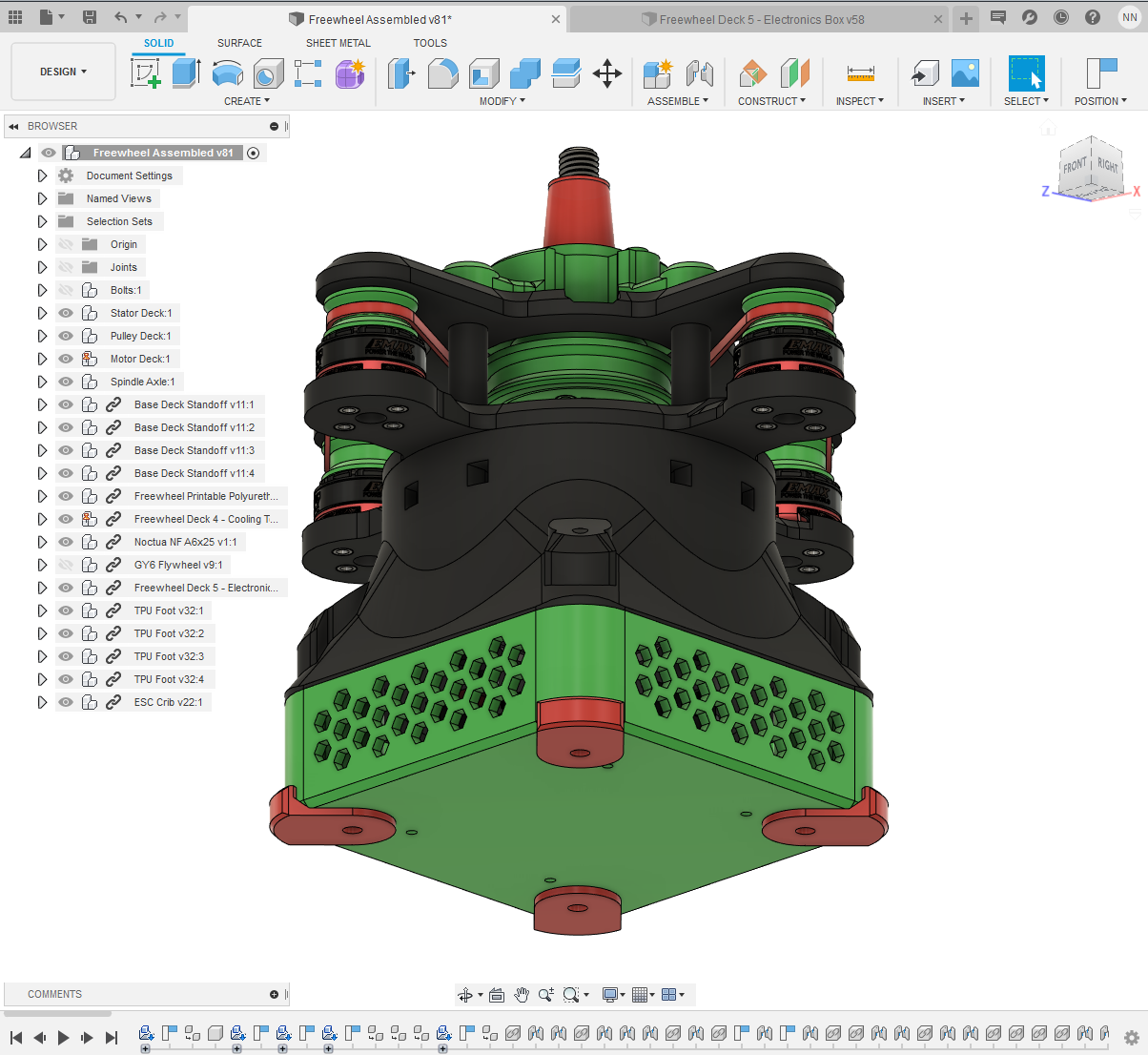
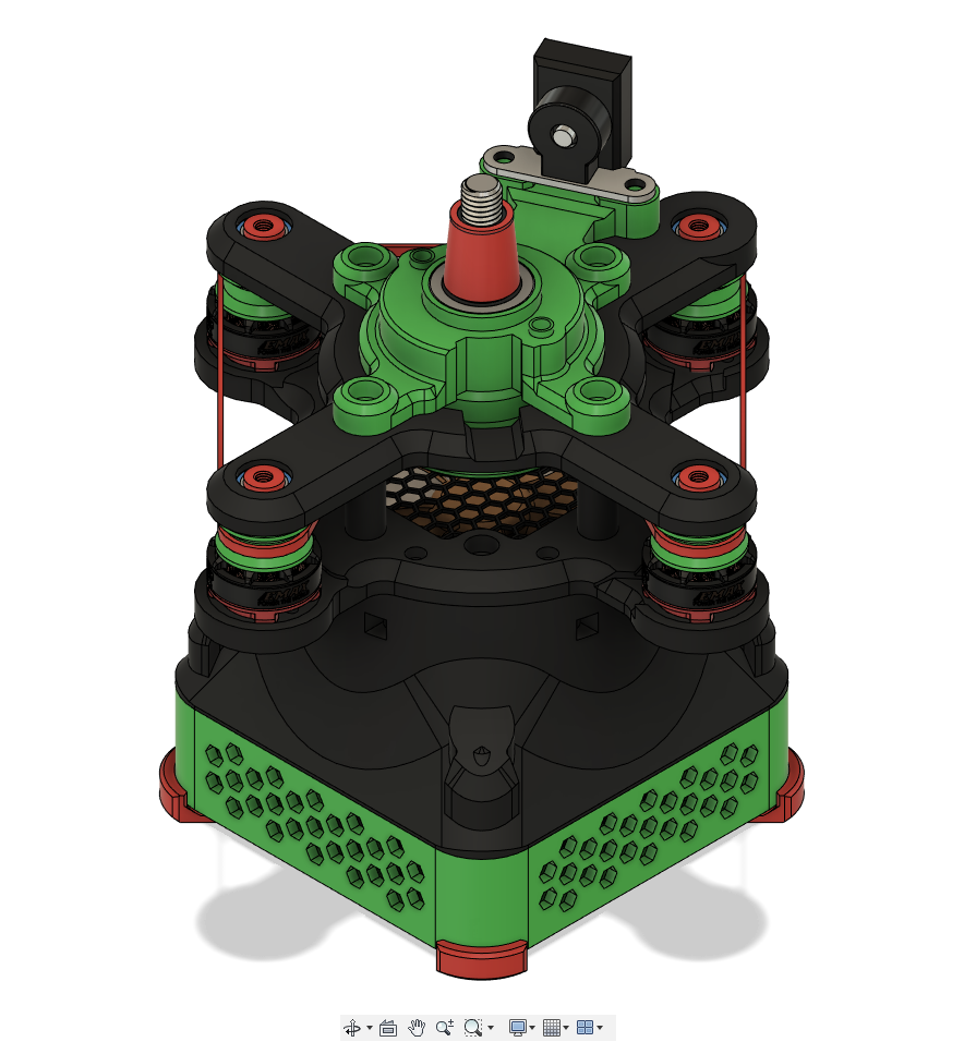
A month later… this is what Freewheel looks like as of today (12/19/2020).Not yet spinning on it’s own power, but we’re getting there.

Ok, back to the original post…
The “Freewheel” Version 2 Bench Tester
Let me introduce you to our new testing device, nicknamed “Freewheel”. The idea is to be able to physically spin up an actual rotor / flywheel (around a mounted stator) combination. With variable control of RPM. This will let us deal with more real-world dynamics of the engine’s charging system at work while loading it down with the injection system at various “engine” speeds and scenarios. While allowing finer control, closer monitoring, and less headache than being on an actual engine.
The design is modular. So when it comes to expanding compatibility, the charging and timing components from different bikes can be tested by swapping in a corresponding crank taper adapter and stator back plate.
The first job for Freewheel is to help determine if we can reduce the 5 amp minimum power requirement of pressurizing fuel with standard fuel pumps (more on that below).
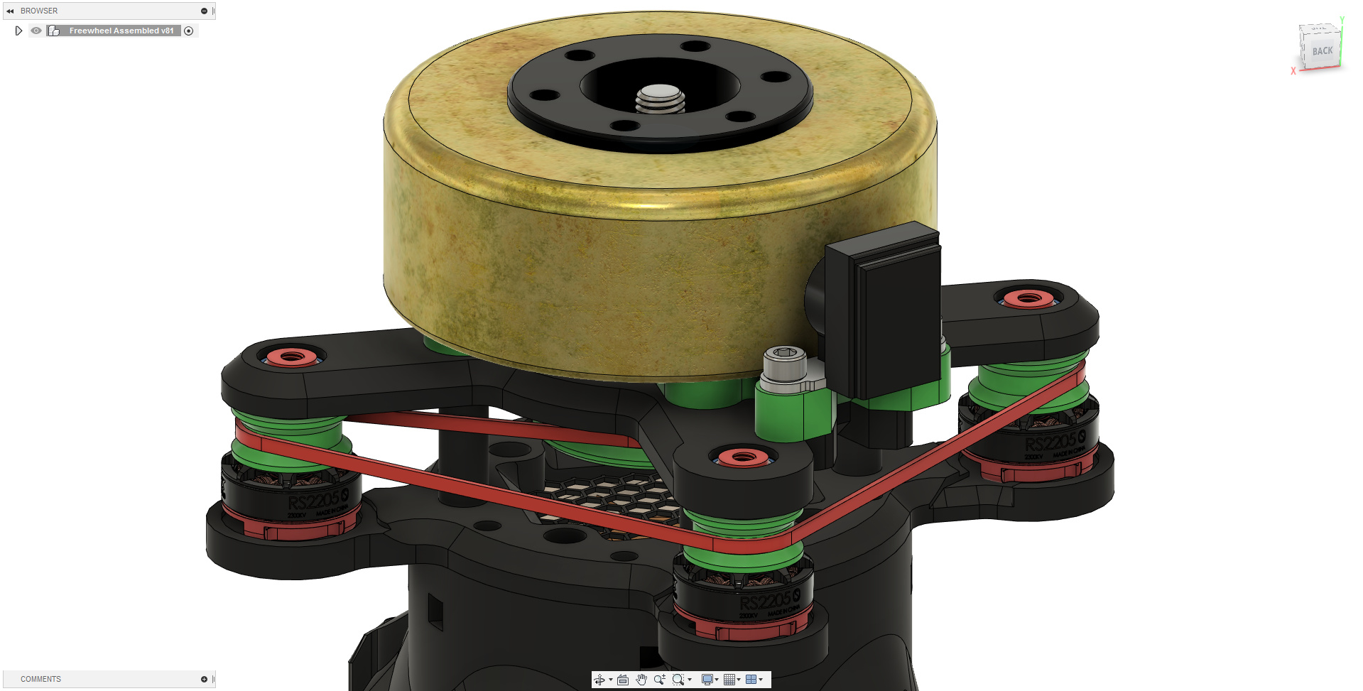
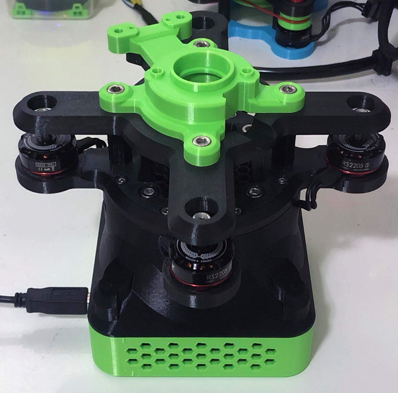
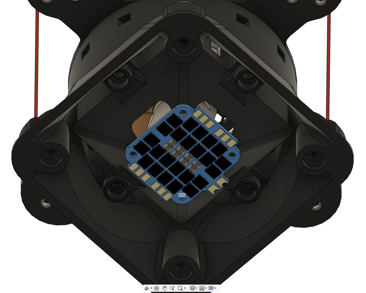
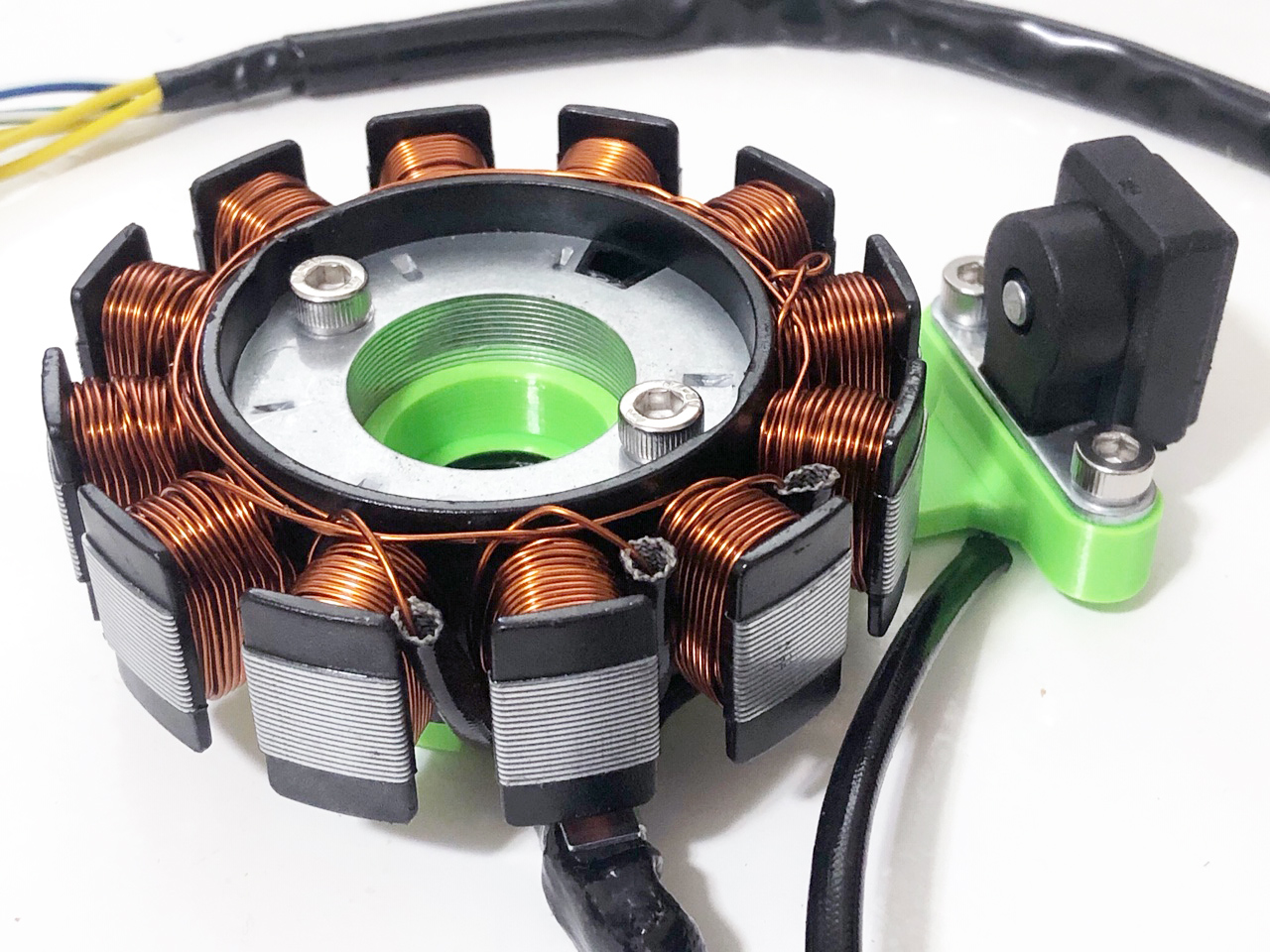
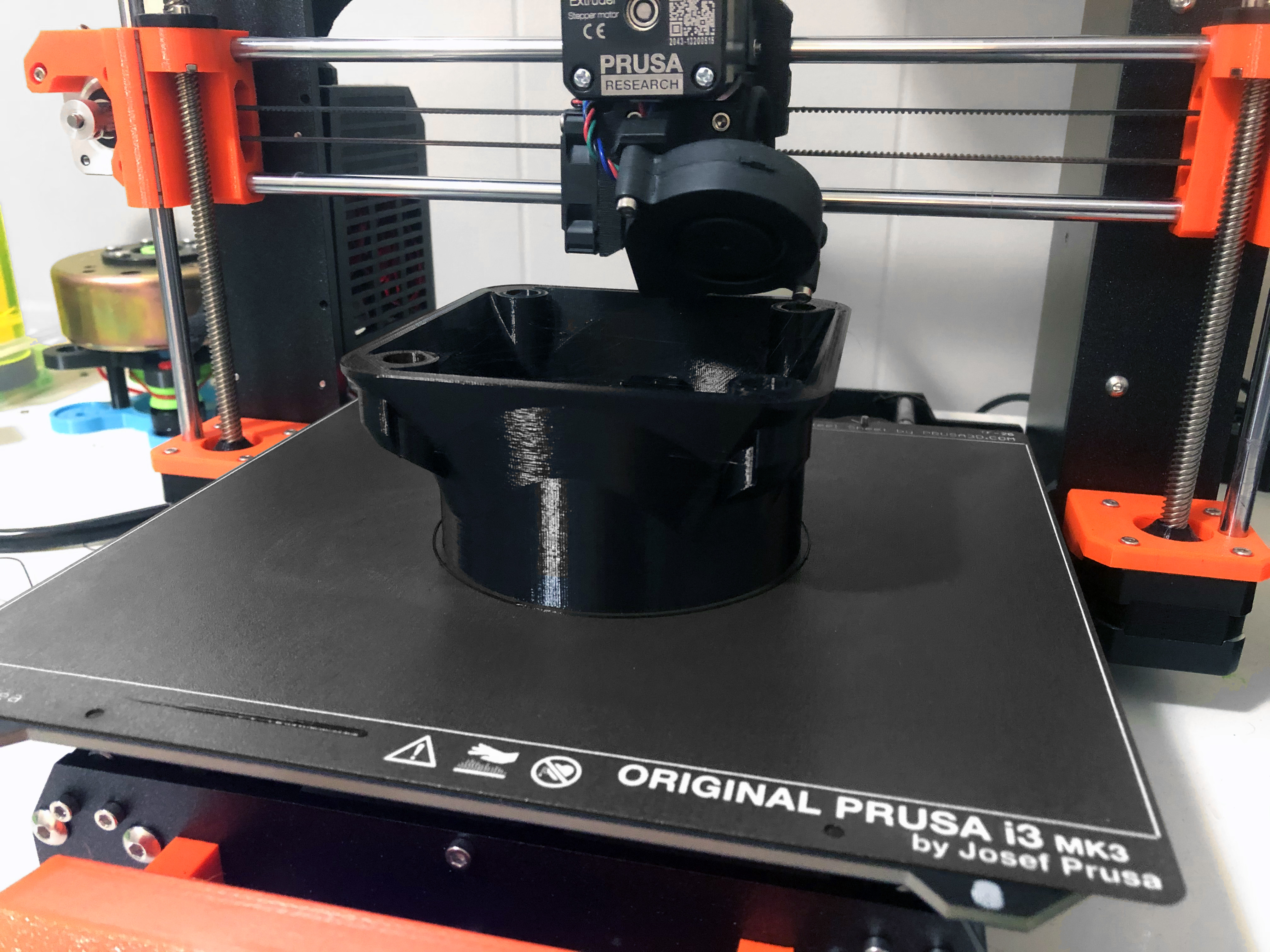
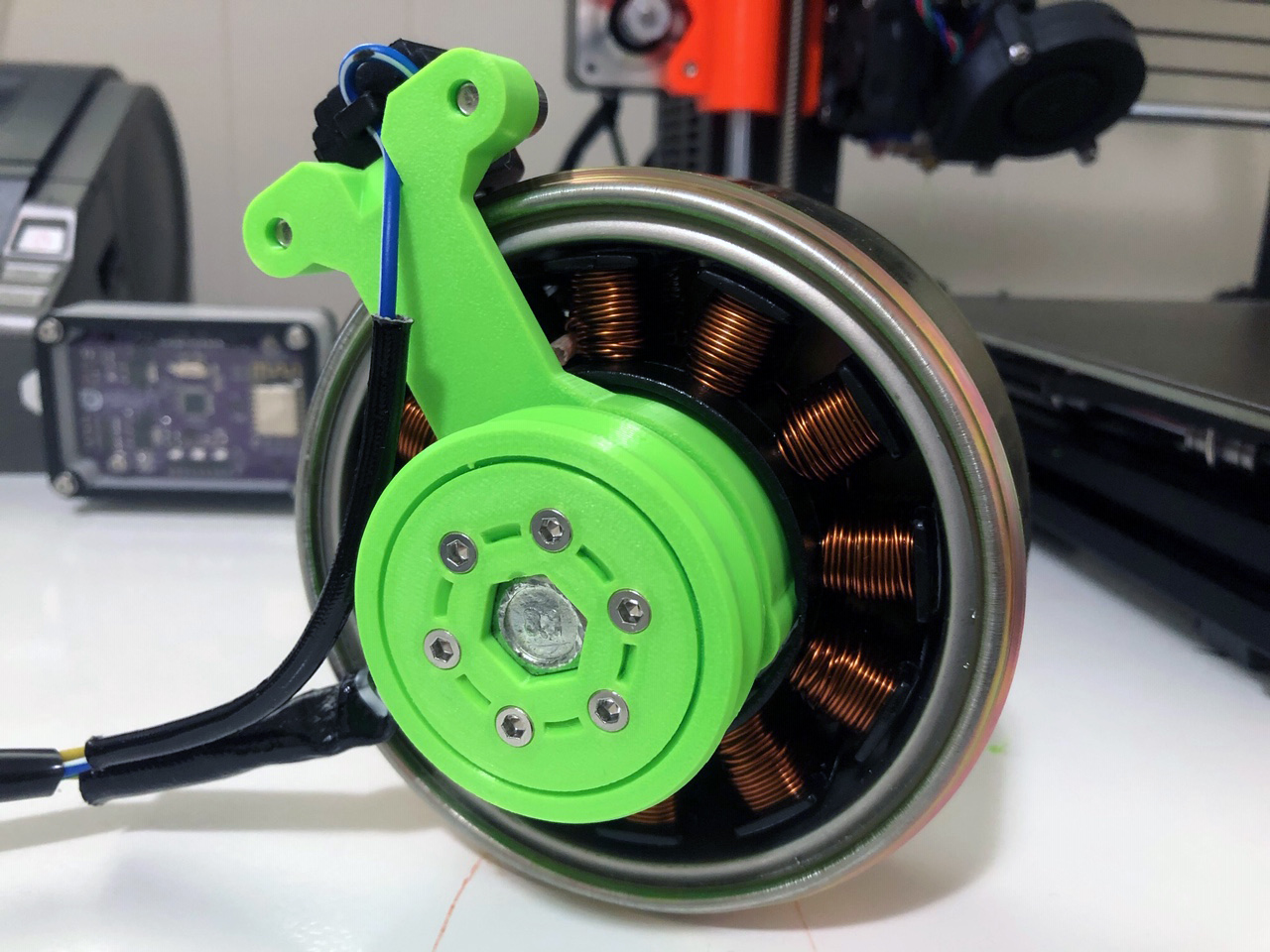
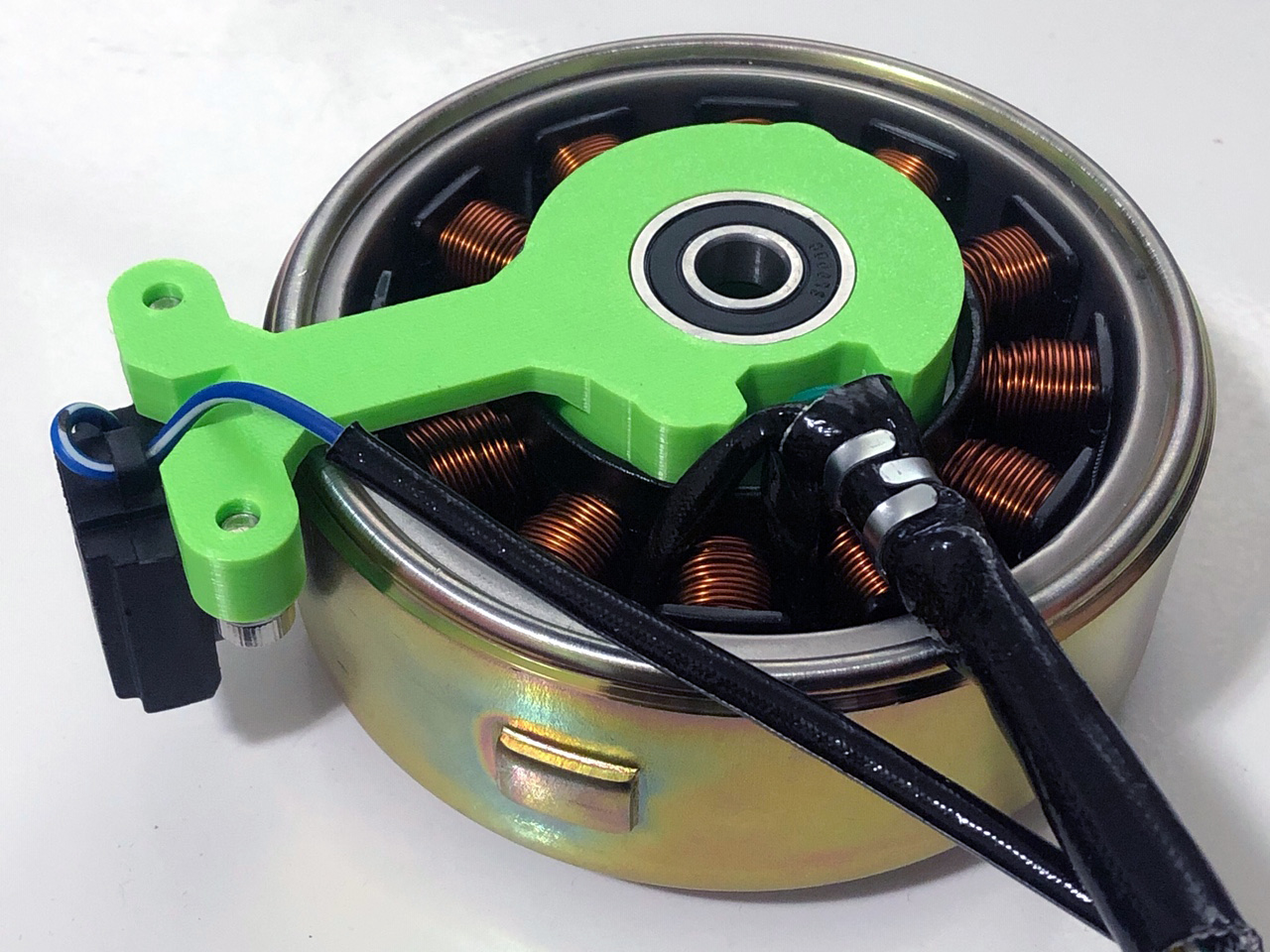
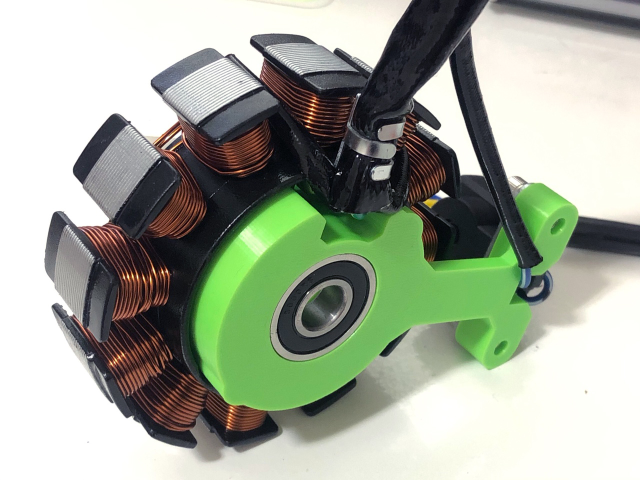
Here’s a teaser showing what has been printed and assembled so far:
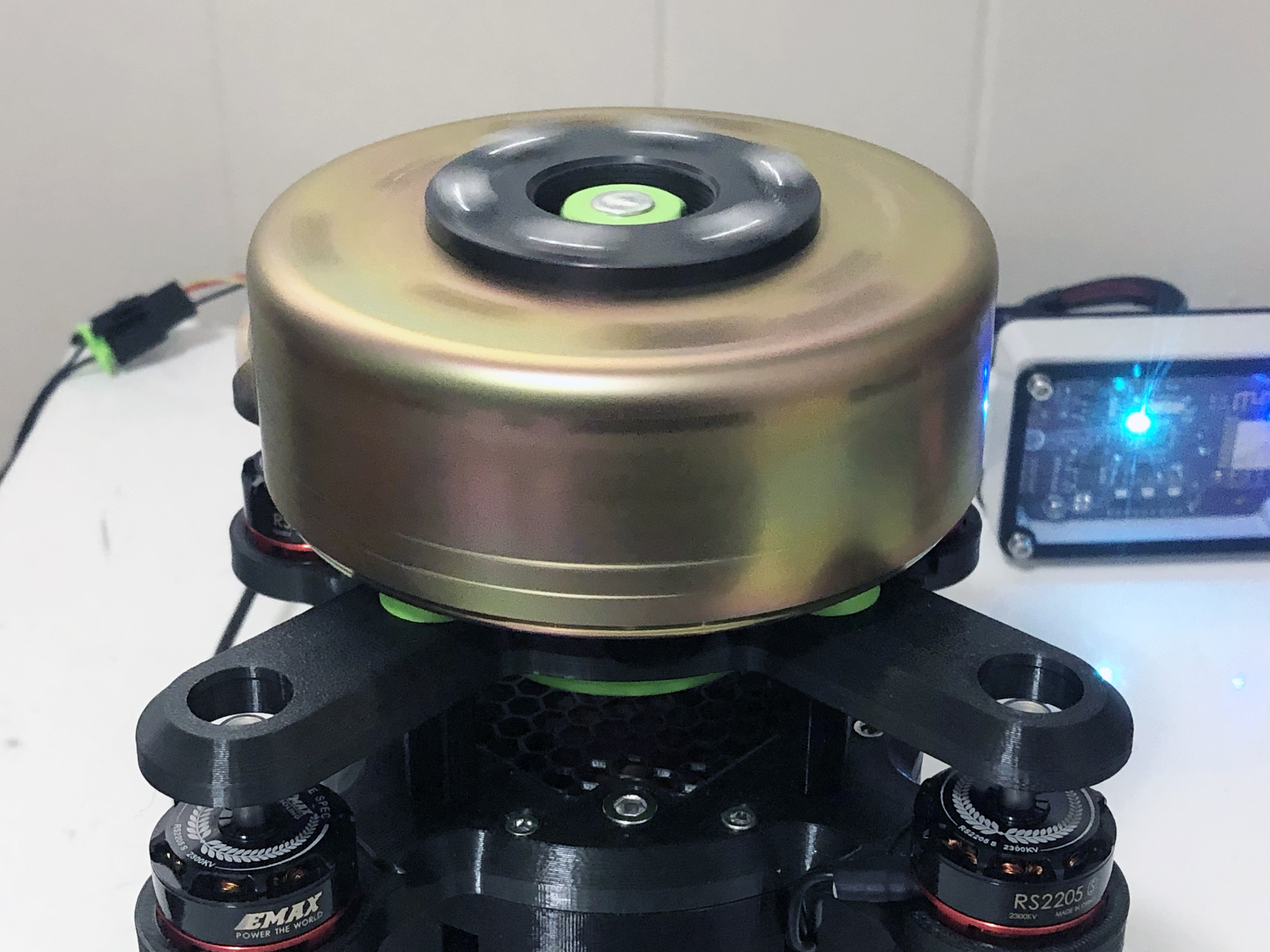
Pictured is the GY6 12-Pole three-phase stator and rotor/flywheel.
Our target RPM range is 0 to 10,000 RPM. I built a similar tool years ago with a 1680 RPM fixed-speed AC induction motor, however this time brushless RC motors are being used in order to vary the rotor speed and tweak other parameters in the motors’ ESCs.
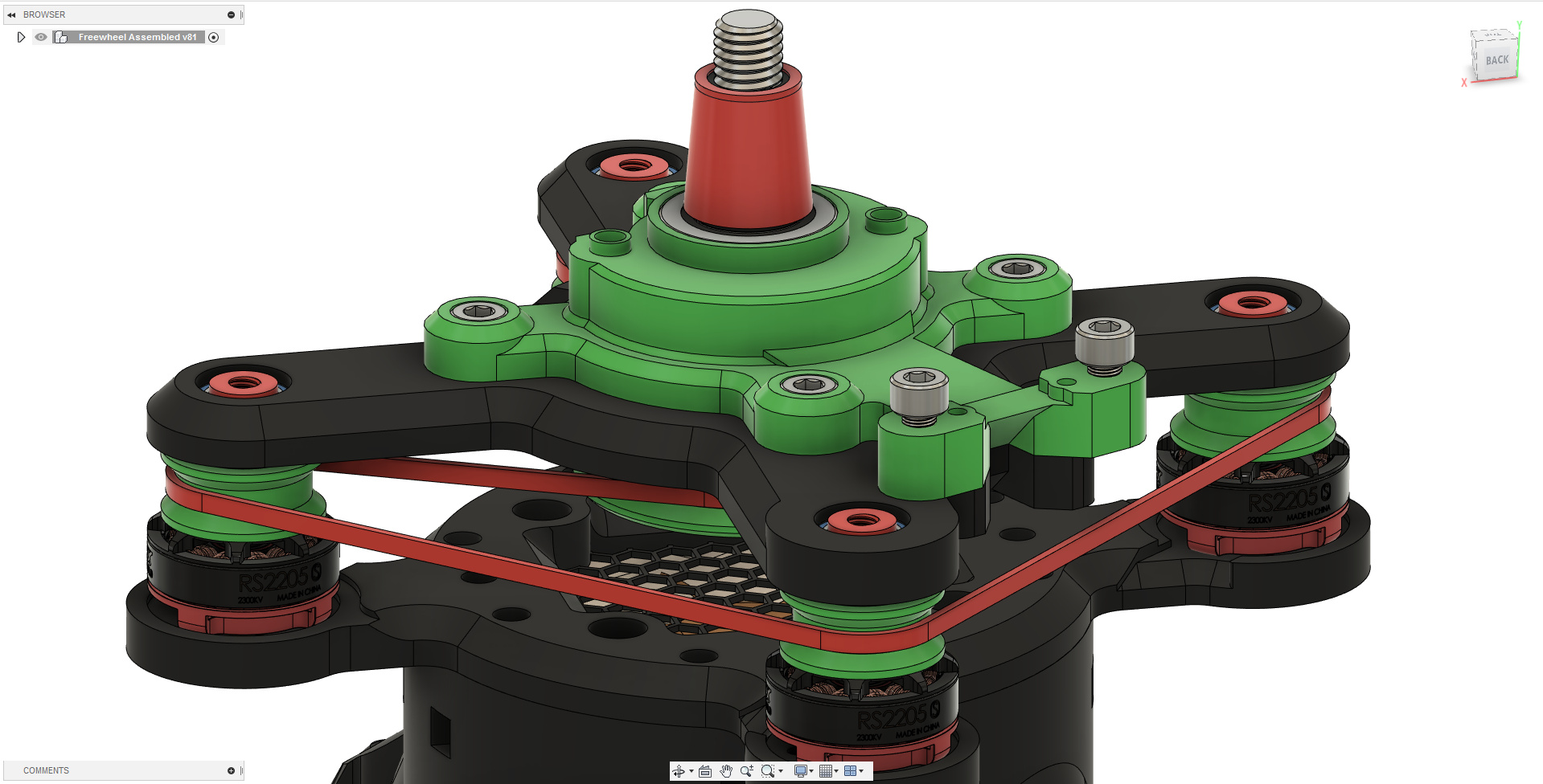
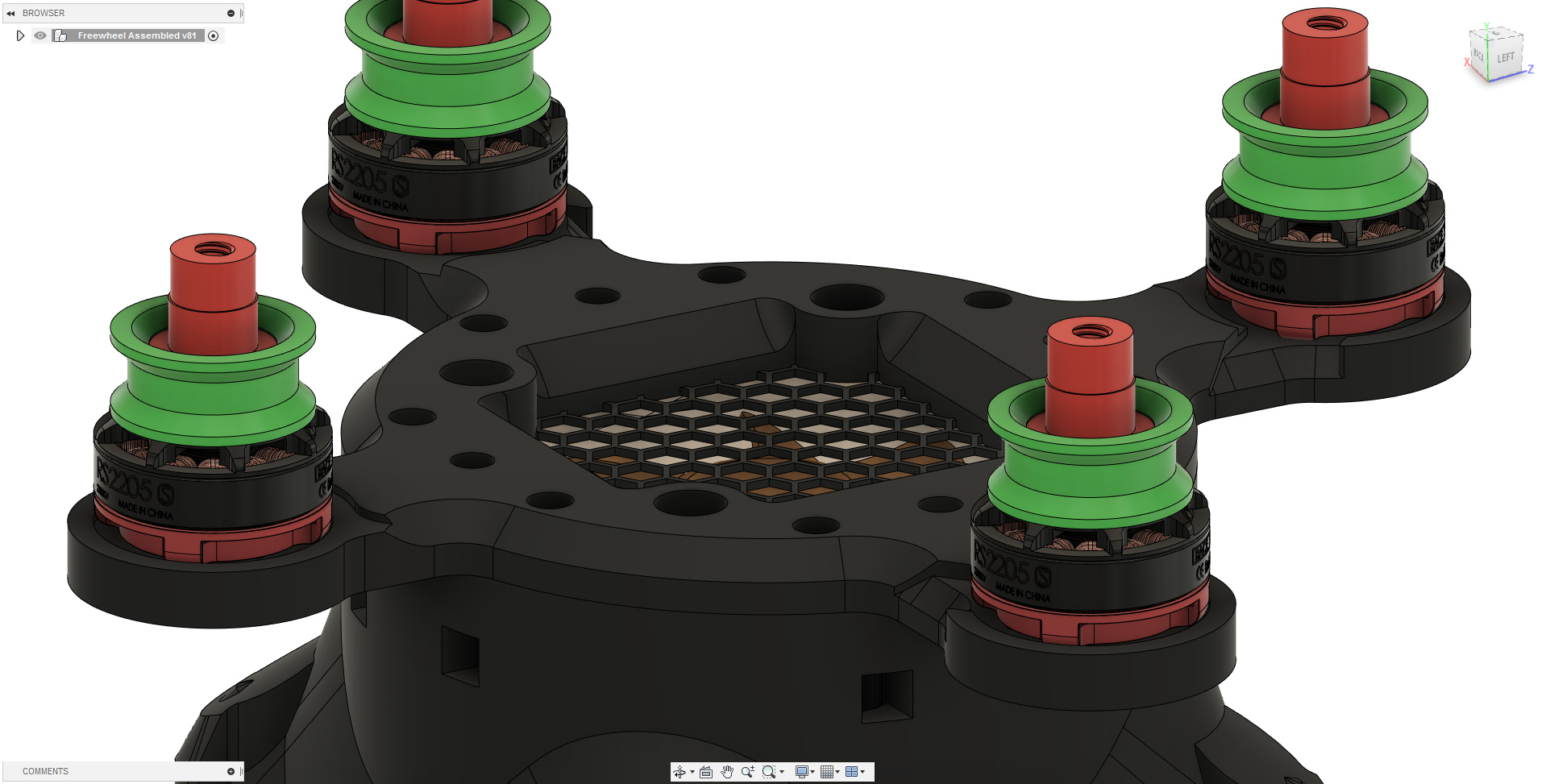
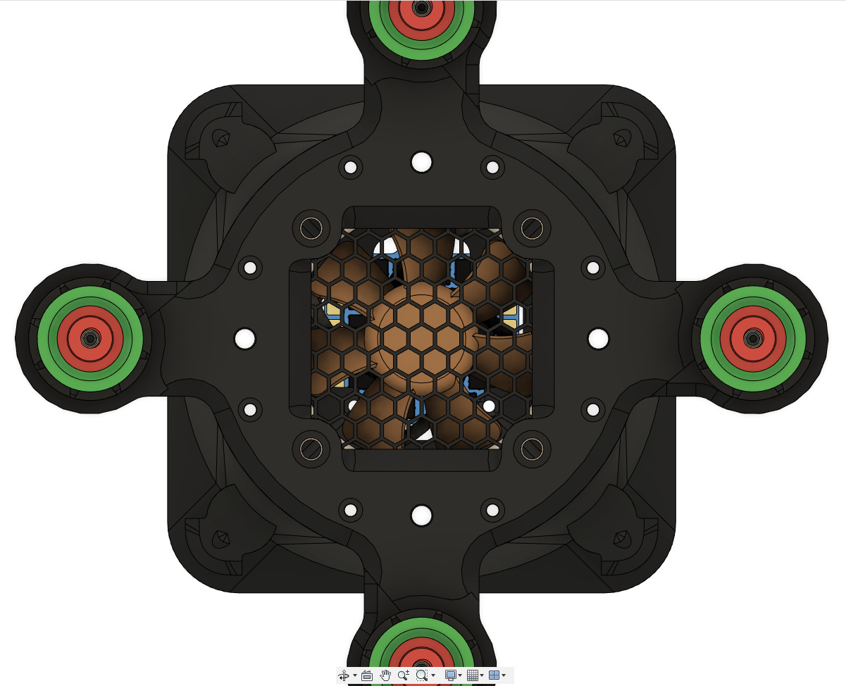
I’m I bit further ahead modeling than what’s been printed so far. The plan is to start with a single brushless EMAX MT2204 motor just to spin-up to rotor, then increase that to a total of four to six motors and a single serpentine belt capable of driving load tests.
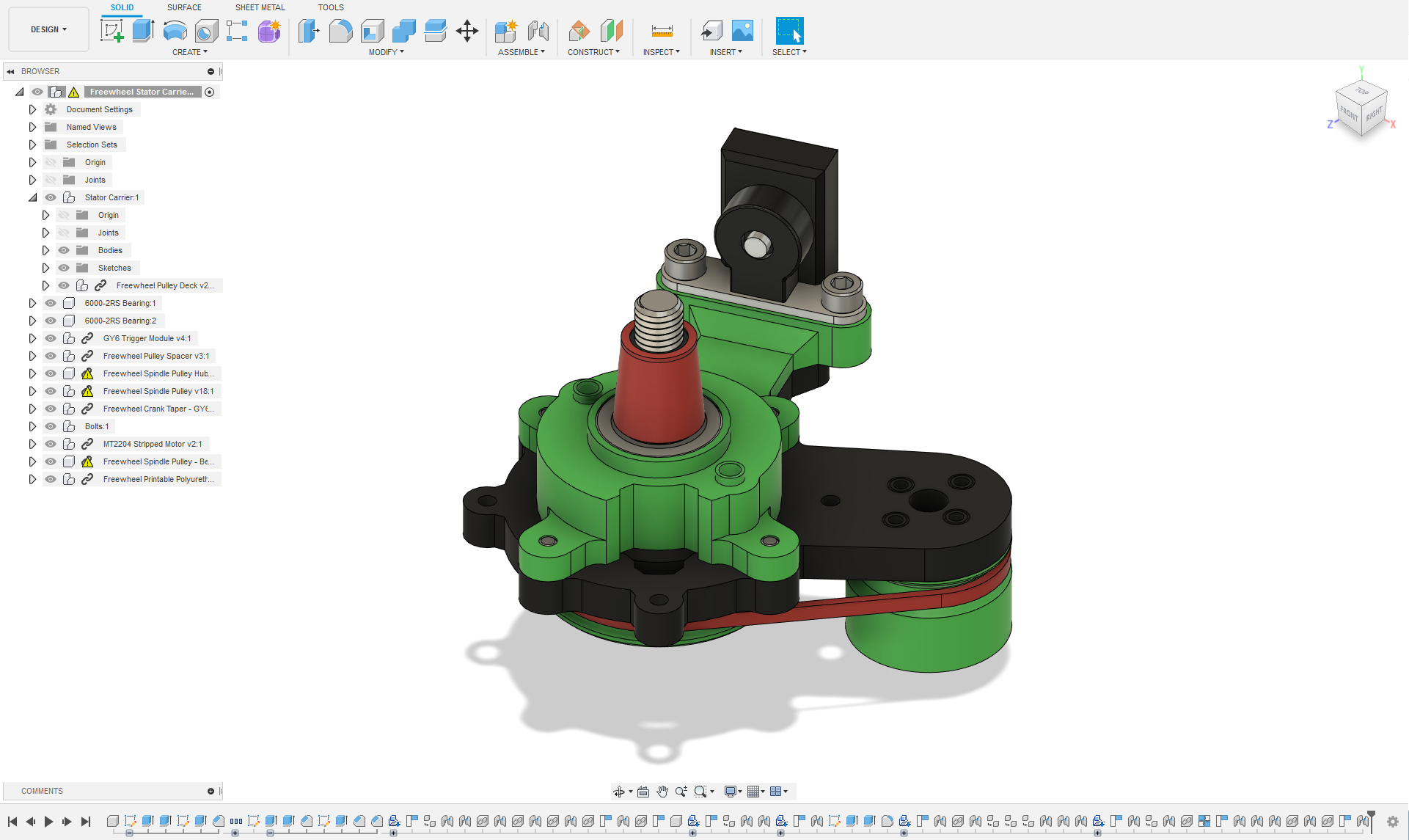
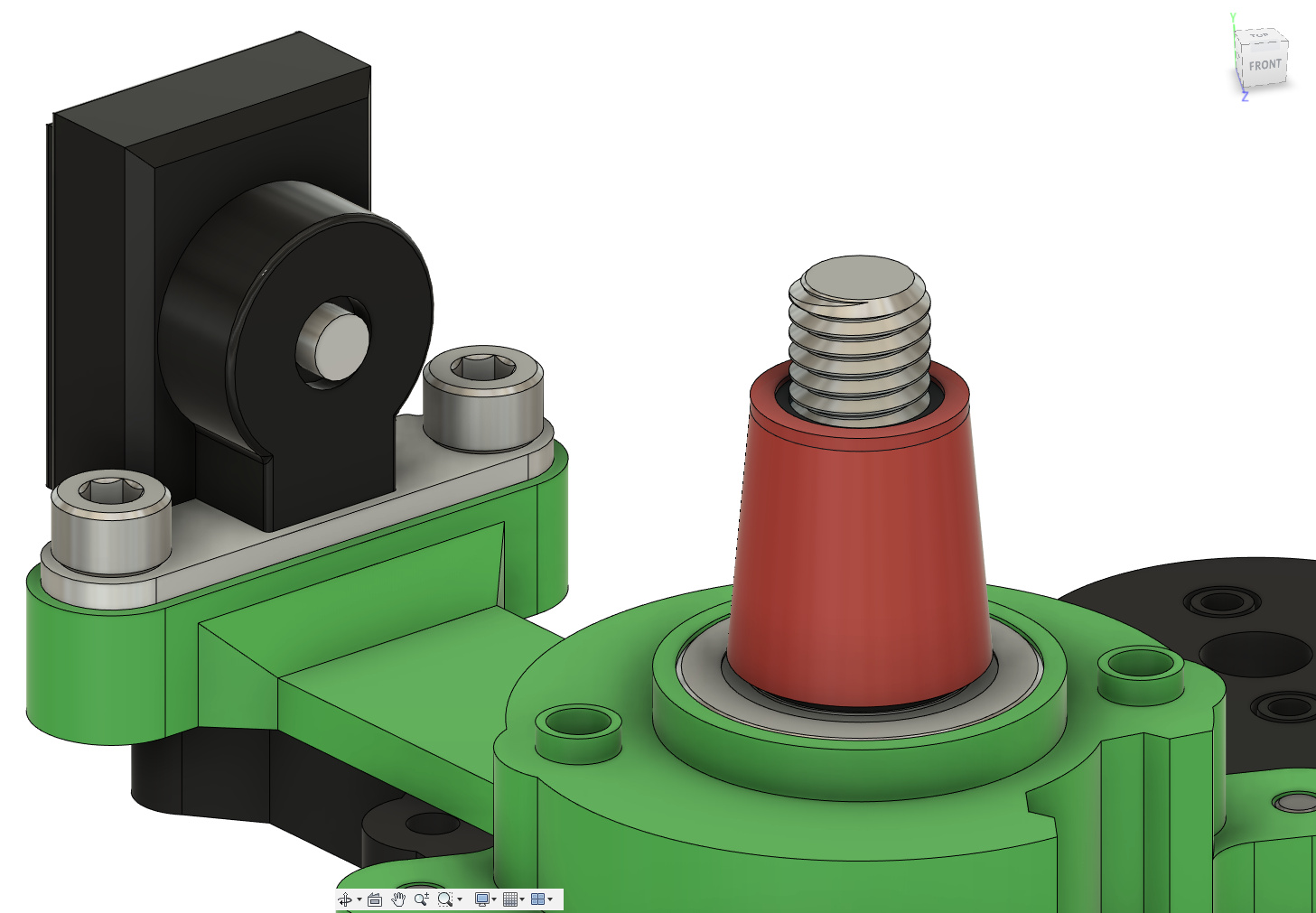
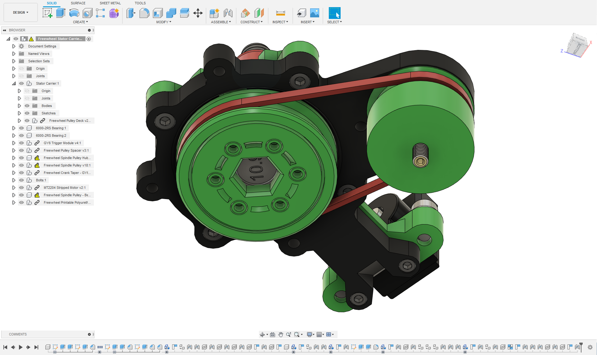
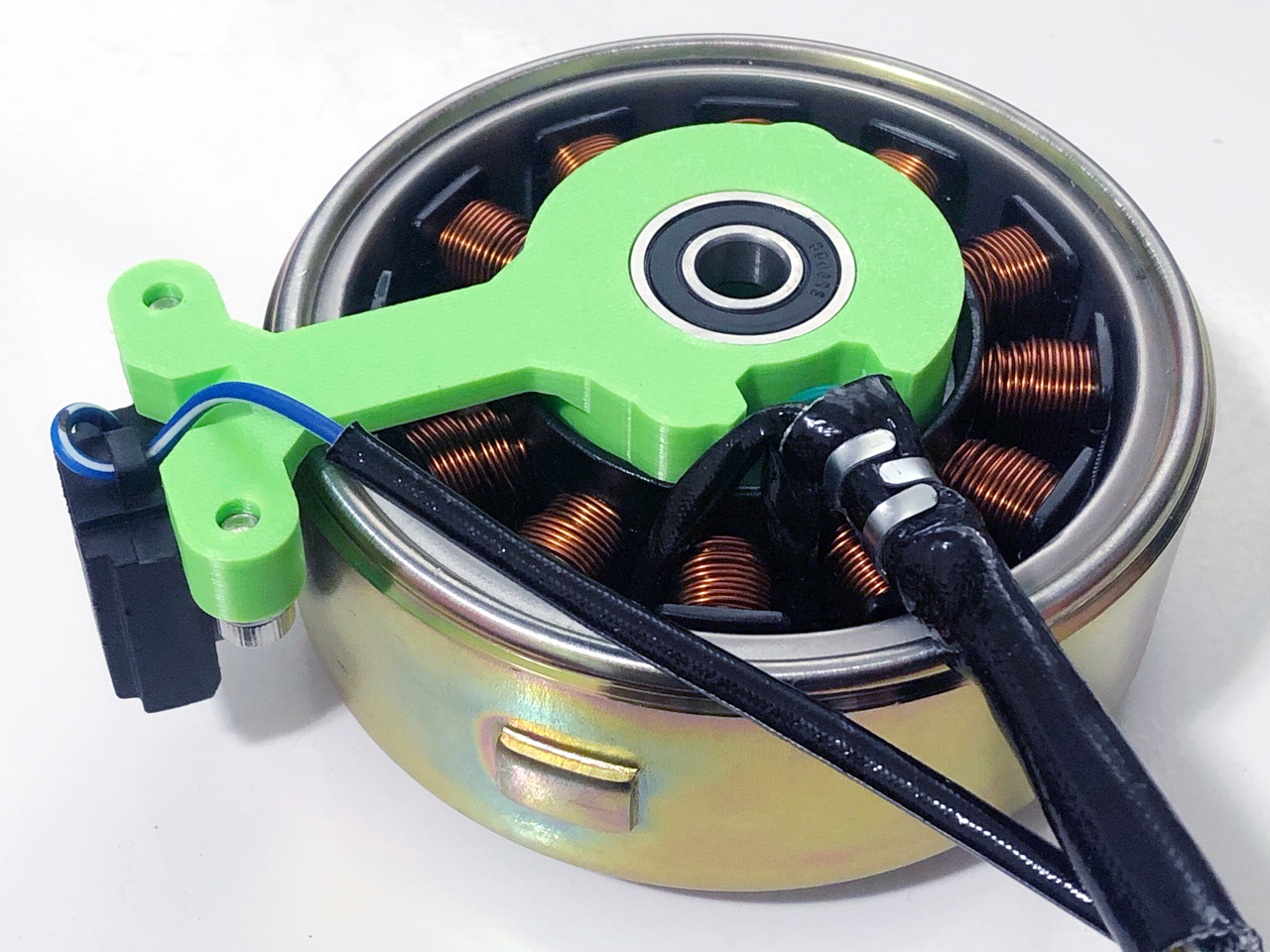
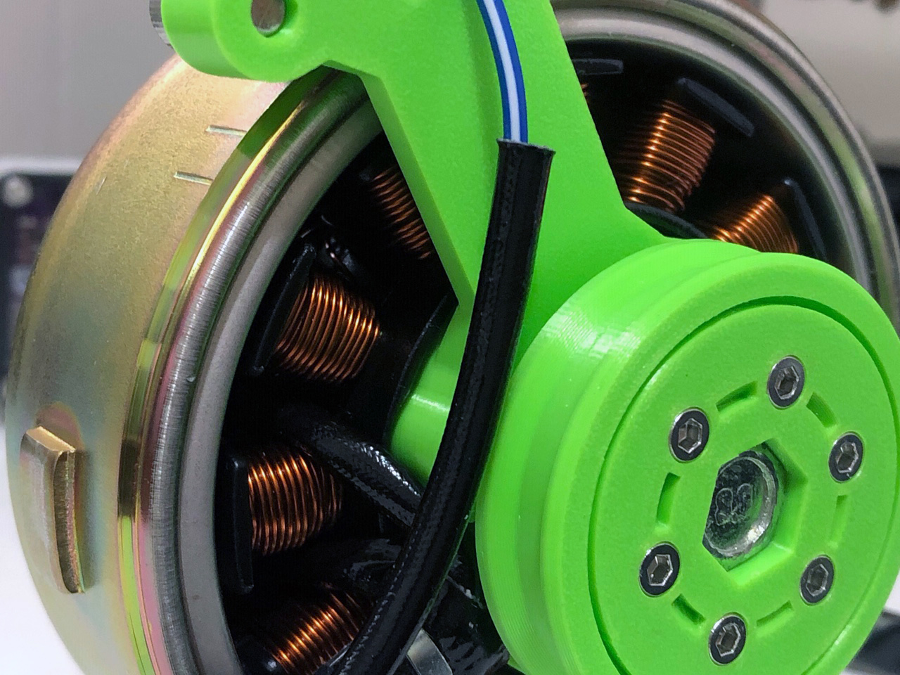
I probably should have printed in contrasting colors so you’d be able to better see what’s going on. What you’re looking at is the assembled stator carrier, bearings, crankshaft taper adapter, spindle, hub, and pulley. An M10 bolt is used as the axle riding on double 10x26x8 6000-2RS bearings, with the pulley slotted to capture the hex head of the bolt. That way, we keep things from slipping under load.
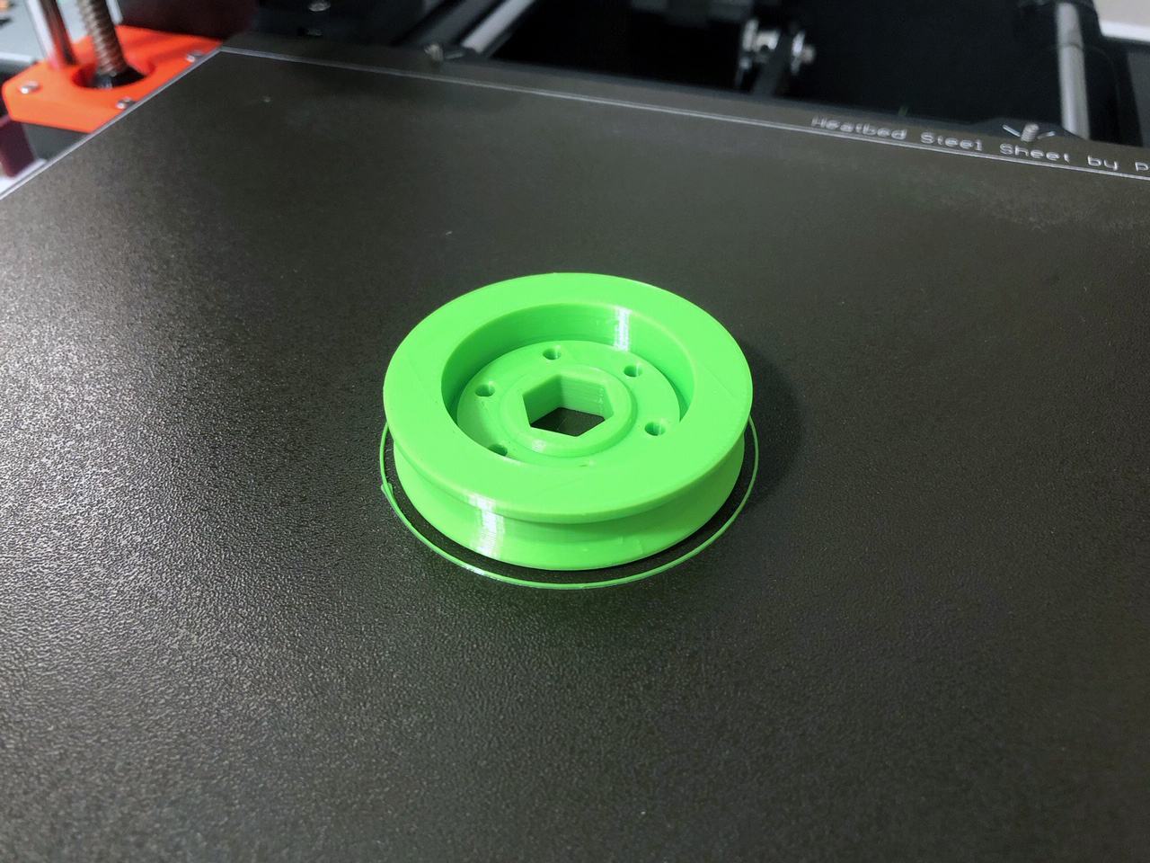
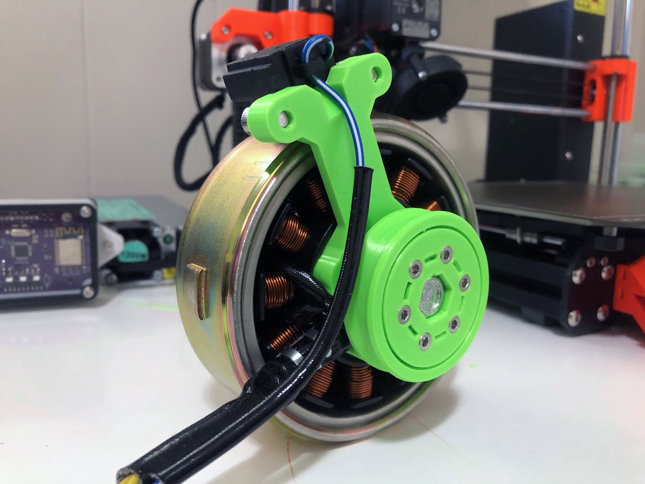
The rotor spins true and motion is fluid (with cogging from the stator of course). If rotated by hand, it produces a small measurable current. Next up are the base, including a pulley deck and motor mounts. Here are a few more pics:
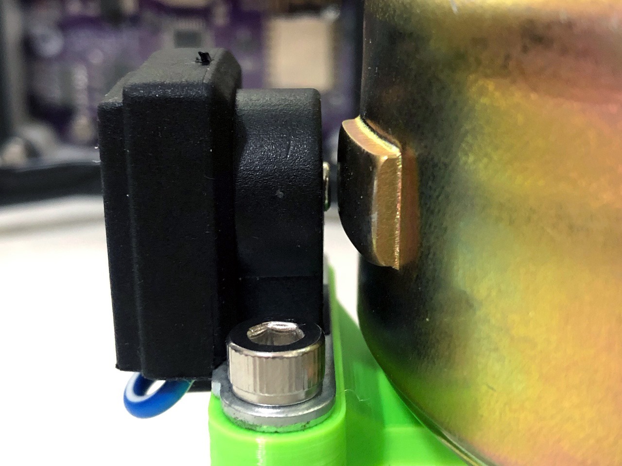
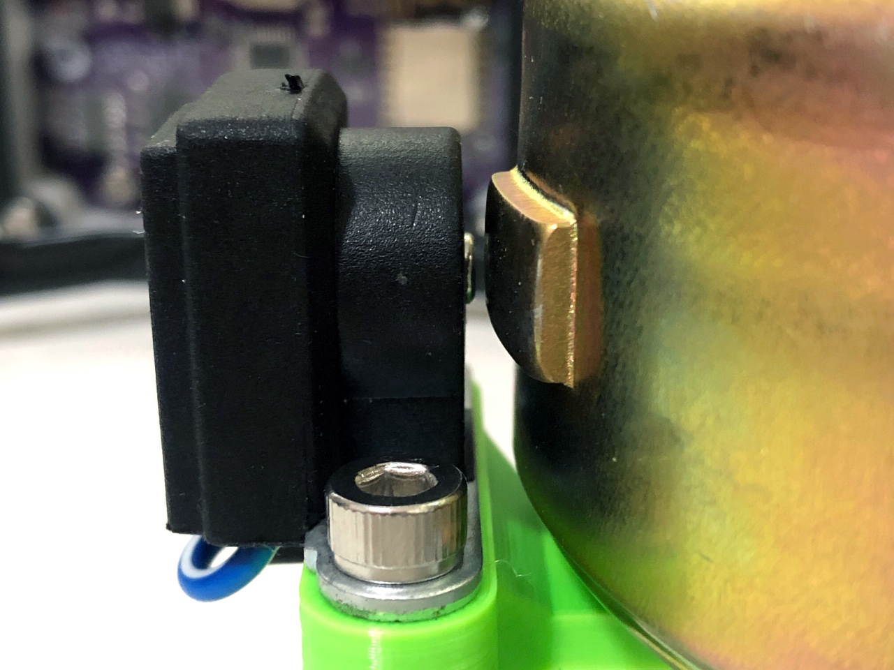
Plus, a mount for the trigger sensor, so more controllable ignition timing tests will be on the menu as well. Will need to add a ground lead.
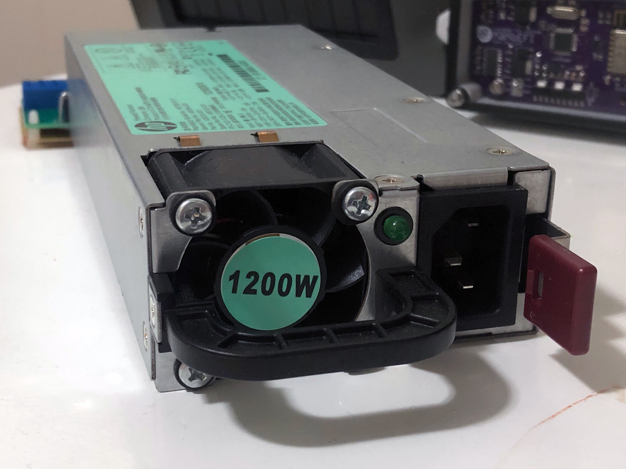
For power we’re going with a retired/recycled HP server power supply. This one in particular is the HSTNS-PL11, capable of delivering a whopping 62 amps of 12v DC output (100a on 240v input). They’re an incredible value at around $20 for the 1200w model, or $15 for the 750w version.
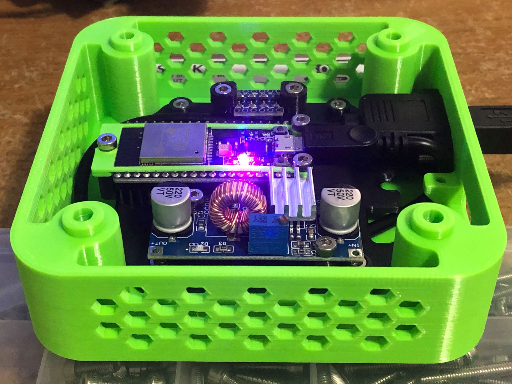
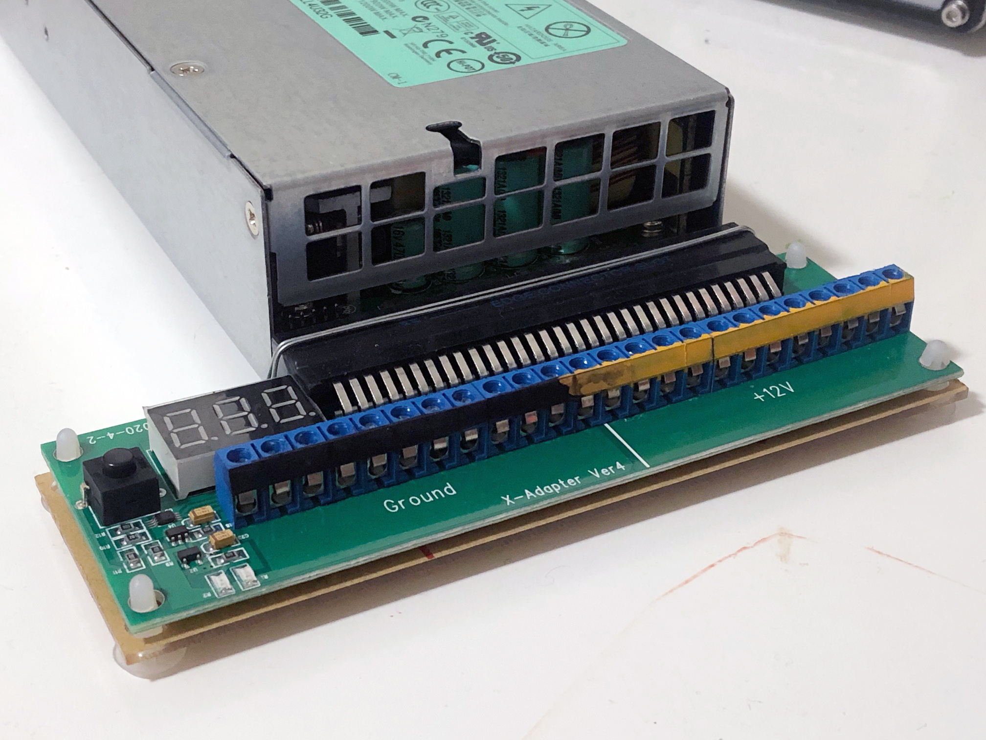
And a breakout board to make life easier:
A cheap current shunt ammeter package for readout:
https://www.amazon.com/gp/product/B08BCD5J81/
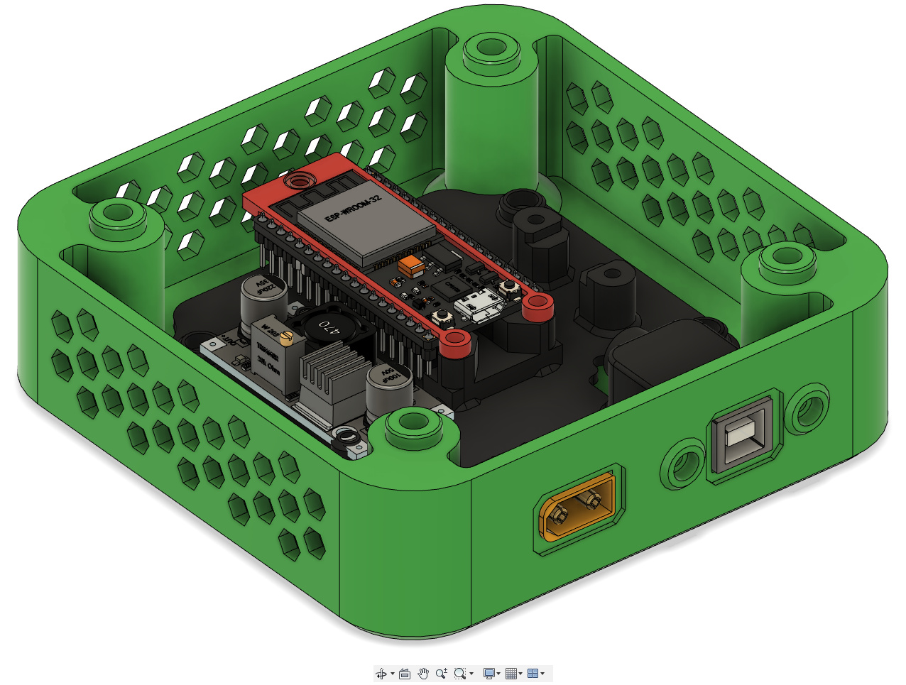
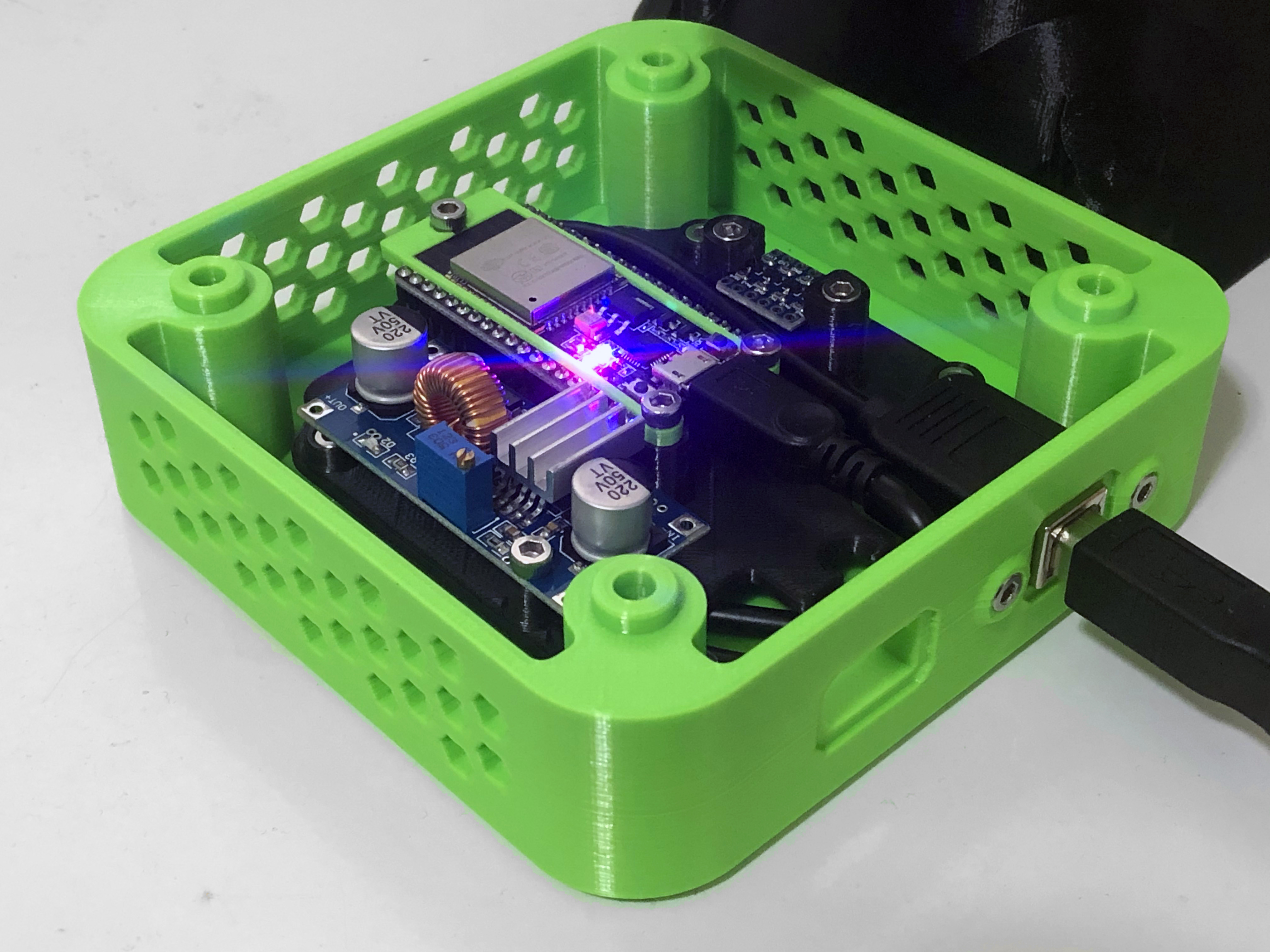
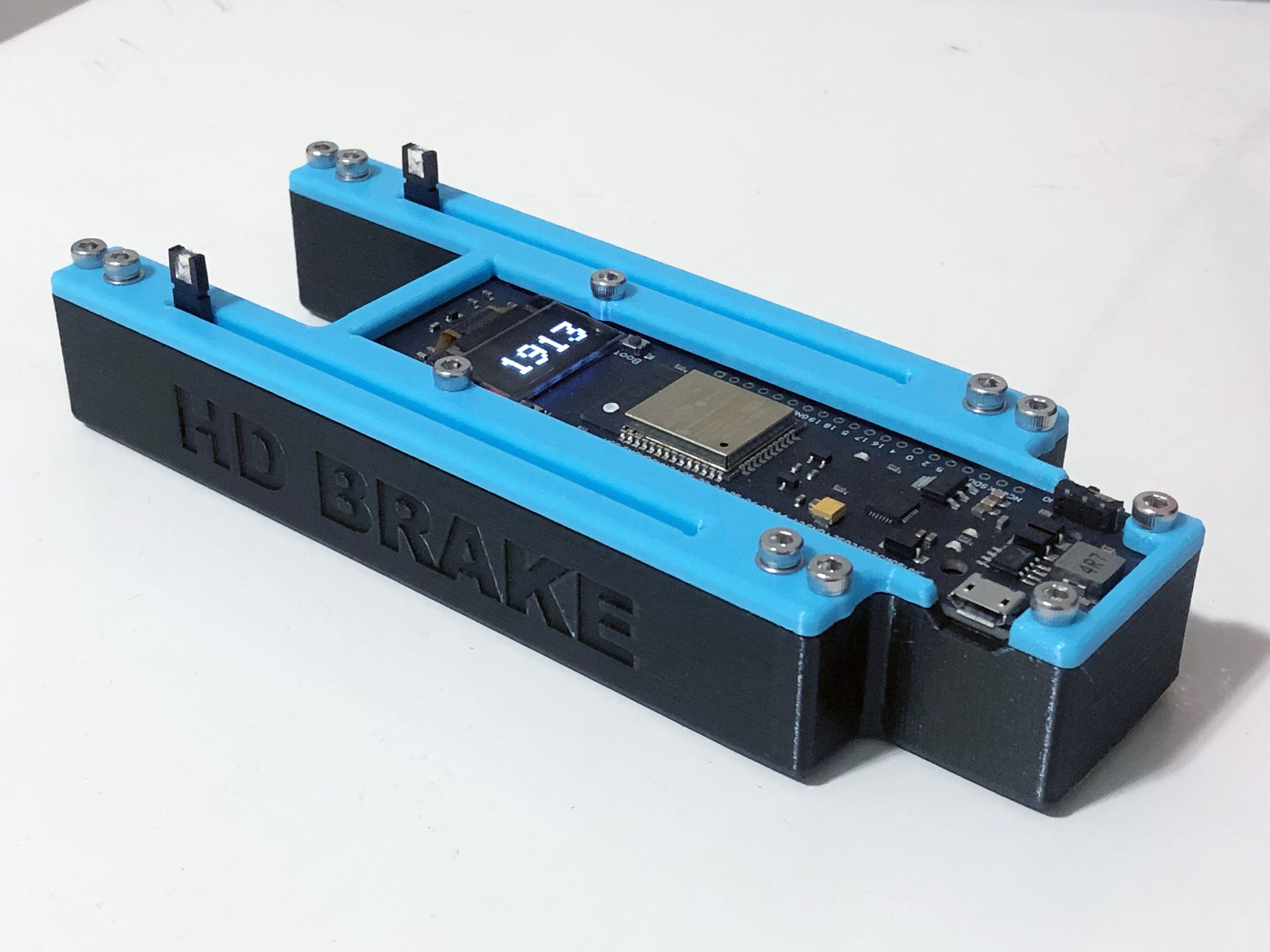
And finally, to control the show we’ll go with a variant of the Tuning Fork wireless controller.
- “Throttle” channel varies the rotor RPM;
- “Brake” channel varies the resistive load bank.

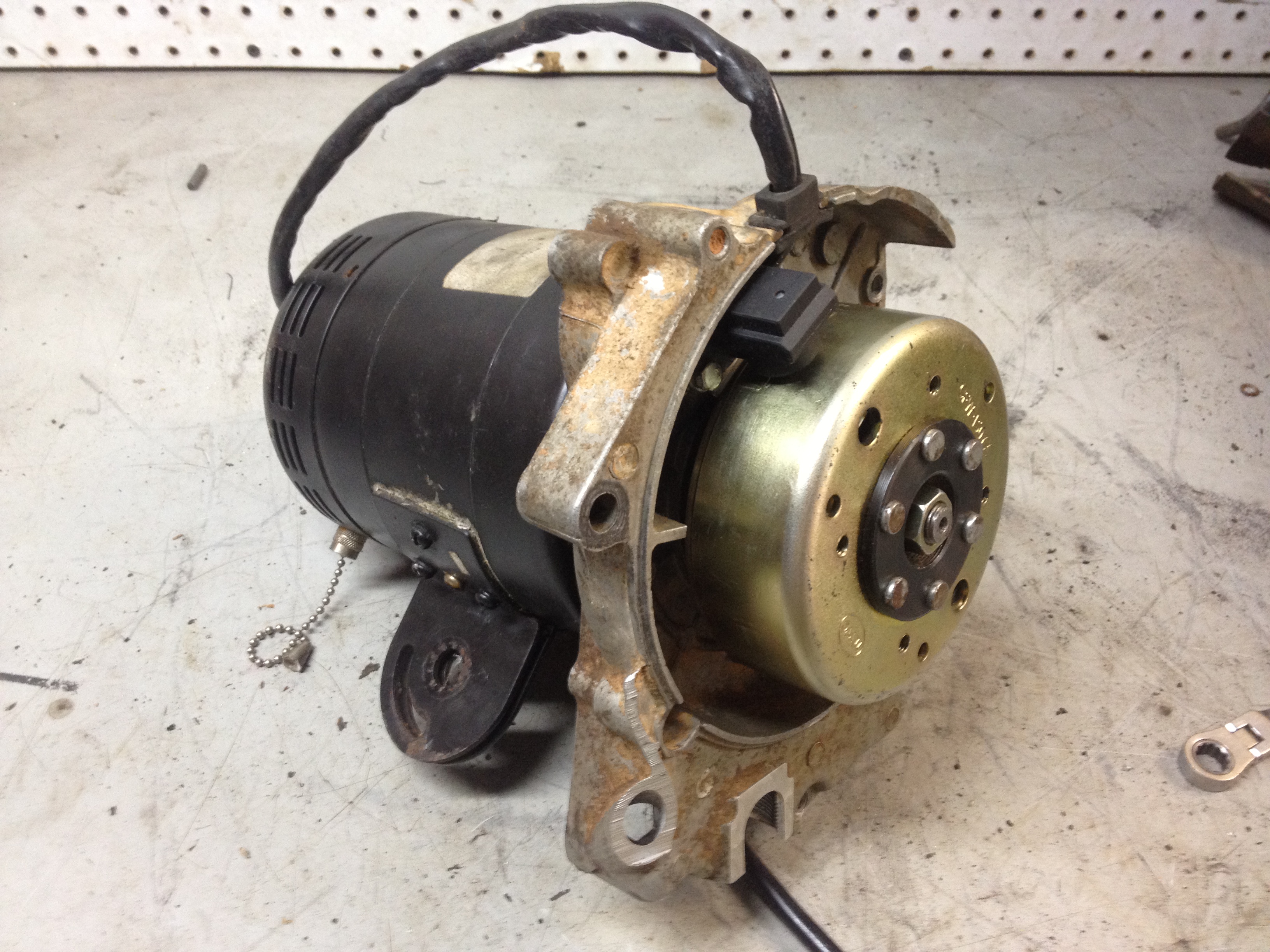
Old “Version 1” of Freewheel (Fixed-Speed)
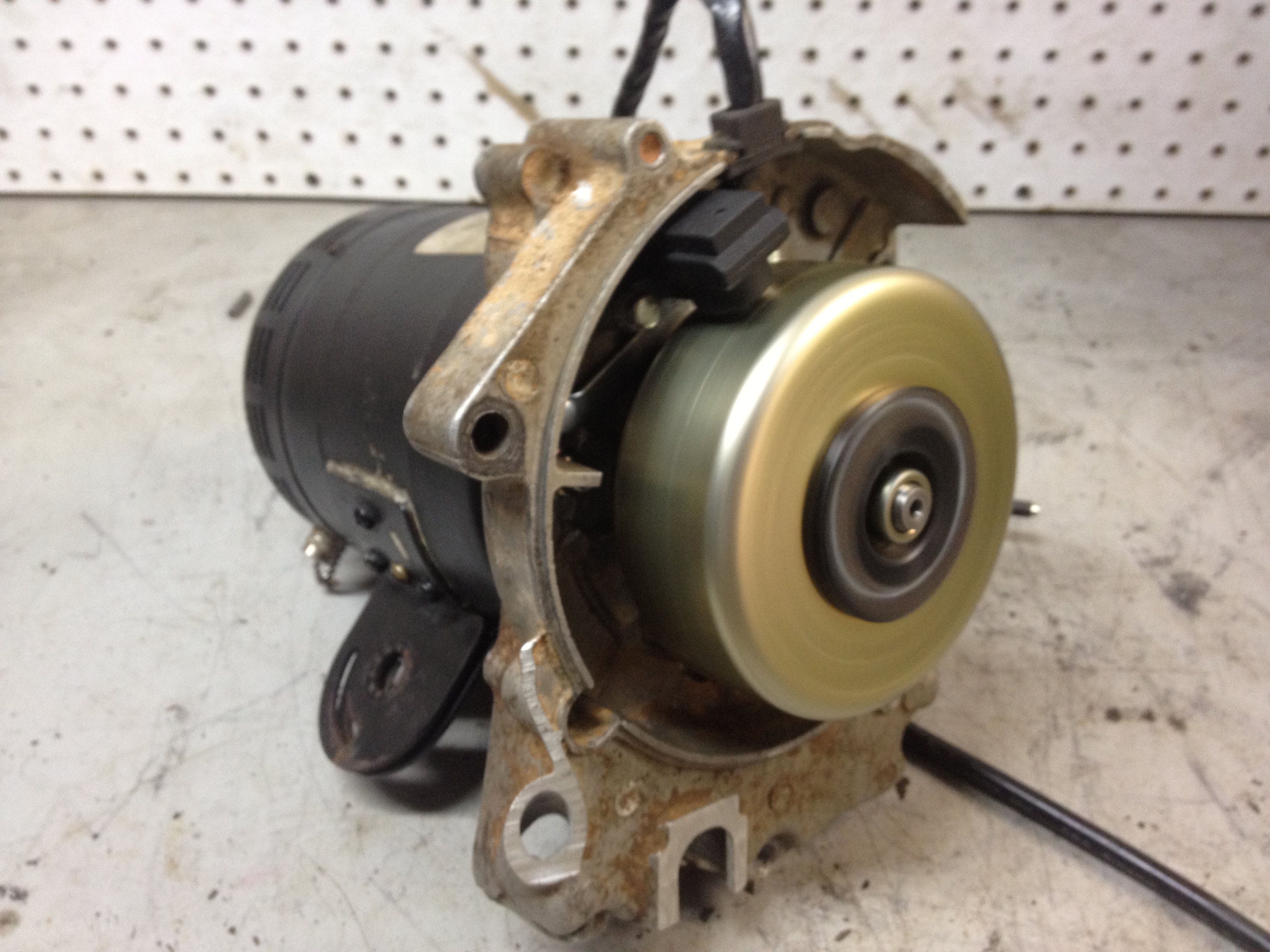
Check out this old junker. Years ago I needed a way to live test complete wiring harnesses, and landed on a similar solution. It was capable of powering the test rig at idle speed (around 1680 RPM I believe), and for testing spark.
To build this dinosaur, I pulled a fixed-speed induction motor was from a wobbly shop fan. Then machined down a crankshaft end, and old crankcase. And installed the stator and rotor. It’s still going strong, though rarely used now.
Fuel Pumps and Minimum Charging System Requirements
Freewheel will will help us explore how to deal with low power charging systems.
The amount of power required to run a fuel pump is an issue I’ve known we’ll need to deal with for some time. The charging systems on small engines often don’t have the juice to power a traditional injection fuel pump. If you’ve been around for a bit, this has been the reason I’ve been estimating 5 to 6 amps minimum to support NanoEFI for a while.
However, I believe we can lower this significantly with an active PWM control strategy. That is, varying fuel pressure (and inversely injector duration) with charging voltage monitored and used to determine when to switch between normal and low power mode.
This has been on the chalkboard for a while, having added a VBAT analog input and added PWM functionality to the HICO1 channel some time ago.
Our first test candidate is a fuel pump from a CBR600. This represents the standard turbine-style pump very common on injected vehicles these days. This particular pump is both affordable and widely available. Most importantly, it’ll keep us on track for NanoEFI’s target price point.
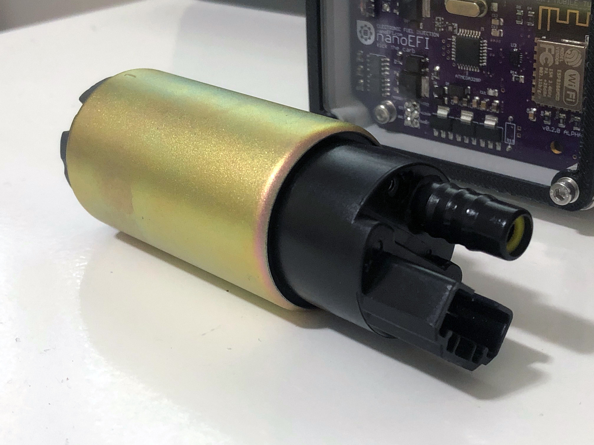
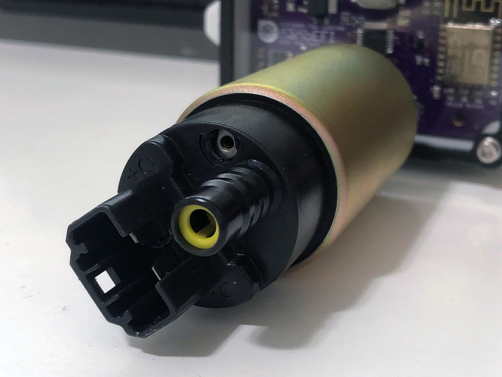
It’s originally designed for in-tank use. Now of course we’ve all heard that heat issues may arise if converted to operate as an external inline pump. As much as that stands to reason at a surface level, I’d rather get some real-world data.
Hopefully we’ll see some good results 
As with most of my updates, expect to see more soon.