Hello everyone  I hope you’re all well!
This update we get to take a break from what I’m sure has seemed like an single-track mind around funding for a while now. The project is in a good position financially and as a result, injection has seen a lot of progress lately. So let’s dig into some new and unfolding technical details!
Recent work has been all about the hardware, completing changes started in the the February board revision, as well as changing over to new more modern processors that are actually available and can be stocked up on, despite the chip shortage.
NanoEFI v0.4.0:
-
Board dimensions reduced:
From 3" x 2" (75mm x 52mm) to 2" x 2" (52mm x 52mm);- 2-layer board stackup increased to 6-layers,
- Most 0805 and larger components replaced with 0402 and 0603 equivalents;
- 24-pin sealed automotive ECU connector added;
-
Main processor changed:
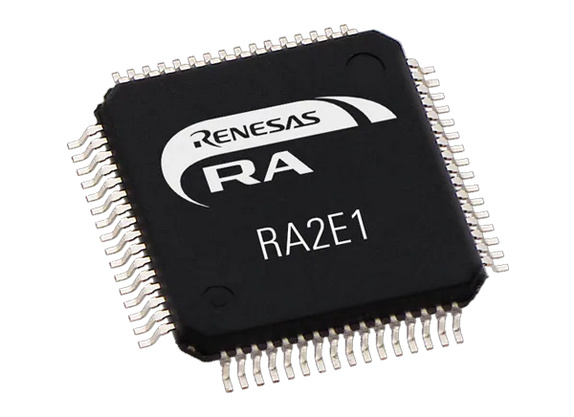
Aging and unavailable ATMEGA 328p processor replaced with Renasas RA2E1 48MHz ARM Cortex®-M23 MCU; -
Tuner processor changed:
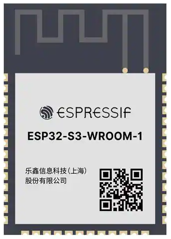
ESP8266 replaced with ESP32-S3; -
PWM Fuel Pump and Injector channels overhauled:
- High current sink/source gate drivers for our low RDSon MOSFETS,
- Active freewheeling circuits to protect the ECU in the case of missing flyback diodes on pumps or injectors.
- Specialized ICs replaced and implemented with discrete components to help deal with effects of the chip shortage going forward.
- Four-wire idle air valve (IAC) stepper driver added;
- 5V rail LDO regulator replaced with switching buck regulator to help reduce board operating temperatures and lower secondary costs related to power in and out of the board.
- 1x Relay channel for fuel safety shutoff;
- CDI ignition driver replaced with logic-level ignition driver,
- Low power key-off state with constant battery connection;
- Accidental 24v jump start tolerance, up to 30v permitted before protection triggers;
- Long duration transient (load dump) protection;
- Reverse battery polarity and negative transient protection, since v0.1 but worth mentioning;
- Significantly better mixed-signal PCB layout practices;
Processor Change: RA2E1 48MHz ARM Cortex®-M23

* 48MHz Clock Speed
* 32-bit ARM Cortex®-M23
* 64 Pins with 56 IO
* 128kB  Flash (Code Space)
* 16kB   RAM   (Running Memory)
* 4kB    Persistent Memory (System settings and tables for active tune values)
* 12x Timers (1x 32bit and 11x 16bit)
* -40°C to 105°C Operating Tempurature
Goodbye Atmega 328p  We had a good run, but it’s over.
Price was initially what lead to a deeper look into the RA series from Renesas. These came in at $1.60 each per thousand versus the $3 to $4 I’ve been seeing for other comparable 32-bit ARM chips from other manufacturers. How long that price will last, I don’t know. But we do have the budget for a price increase after the time cost of porting things over is complete. If this just turns out to be a price incentive for buyers to migrate to the RA platform, well… it worked 
After buying an RA2E1 evaluation kit and running some tests for our needs, I was sold. I went ahead and placed an order for 500 pieces through an authorized vendor for the 64-pin LQFP 128kB/16kB variant. 165 of the processors were delivered right away and are on hand now, with the remaining 335 due to arrive in February.
I wanted to stock up on enough to last us through ongoing chip shortages… a mistake I made with the 328p by not stocking up before the pandemic while they were available. For now I feel like we have a safe quantity of the main processor locked in. Unfortunately, we’ll need to continue spending good chunks of cash to stock up on other critical components as well.
More on that in a later update though. For now, let’s talk about performance.
Clock Speed 

At first glance you might think the nice clock speed boost (from 20MHz of the Atmega) to the new 48MHz would be a dramatic improvement all by itself. However, since almost everything we’re asking the processor to do is run based on interrupts and hardware timers, there will be practically zero difference in the actual meaningful “speed” that you could notice or probably even be able to measure.
If anything, this extra processing margin just means I won’t have to spend as much time right away optimizing code for efficiency and can just get things done (within reason).
Timers 
The most important difference is actually the number of hardware timers. This is what gets me excited.
For our application we need a minimum of four timers:
- A timer to precisely derive engine crankshaft speed from the trigger signal;
- A timer to handle PWM for the fuel pump;
- A timer to flag scheduled ignition and injection events for execution at arbitrary counts/steps;
?. And a fixed timer overflowing at set intervals to keep track of the overall engine cycle timeline, which is calculated from engine speed and may set to 720° for four-strokes or 360° for two-strokes.
That last timer is numbered “?” because the Atmega 328p only had 3 hardware timers…so what to do?
It took some weeks of effort to think through and implement a strategy that made use of only a single 8-bit timer for the last two functions. I landed on a solution which would by default set the timer overflow at fixed counts of 2.5ms intervals to keep track of the overall cycle timeline… and then also call that same timer overflow interrupt at specific overflow+step counts to flag a scheduled injection (or spark) event for execution at the correct moment… and then schedule it to be called again shortly after to turn off the injector at the moment the pulse duration was reached… all without losing steps in the overall fixed count which would throw off the real timing of all other downstream events in the same cycle. It was a pain and took a lot of iterations to perfect, but in the end worked amazingly well. Very proud of the result.
Unfortunately that’s all kinda pointless now, but I’m thankful as that’s not a problem at all for the RA2E1. With the RA’s comparatively ridiculous 12 hardware timers I won’t have to spend days re-implementing the more complex method when porting the NanoEFI firmware code over. We’ll just throw event handling on an extra timer… Wow, welcome to the benefits of using a modern processor 

For now I plan to use one more additional hardware timer to support PWM on the injector channel for v0.4.0, giving us two high-output channels with active current regulation. Won’t cost anything extra, so may as well. The rest of the unused timers will allow for the possibility of new features in the future.
Memory 
Memory limitations were something constantly in mind with the 328p. It only had 32kB of flash memory available for program space (where the code lives). As well as 2kB of RAM for calculating and holding all our real-time variables while running the engine. And a very anemic 1kB of long-term EEPROM memory usable for system settings and tune lookup tables. I won’t go into all the details, but fitting everything into the limited memory was getting to be a problem.
The RA2E1 is much more generous with 128kB of program space, 16kB of RAM, and 4kB of persistent data. I’m really happy about this, or more accurately… relieved to not have to stress as much about every byte.
64 pins are better 32 
I could go on about what we can do with all these extra pins, but for now most of them will just be pulled high or left floating depending on what the datasheet wants us to do. It’s just nice to be a little more flexible on our pin assignments.
Wireless tuner: Switched from ESP8266 to ESP32-S3

Also worth mentioning is the tuner chip upgrade from the ESP8266 to the new 240MHz ESP32-S3. This is pretty much just a drop-in upgrade. We’ll take advantage of the new dual-core architecture to unblock some application processes that would previously get hung up if WiFi signal was lost. And we’ll definitely use its significantly better encryption and security features.
Beyond that, I don’t plan to spend much time working on anything new here compared to the 8266. The framework I’ve built for the wireless tuner works well as it is, so I’m just looking to get ahead of the older chip potentially getting phased out at an inconvenient time later.
Current v0.4.0 Design and Layout Completeness
 = 1. Circuit simulated |
  = 2. Components selected |
  = 3. Physically implemented in PCB layout
 = Will be implemented last, design and layout depends on other board elements.
-
Power and transient protection
- Accidental 24V jump start tolerance

- Load dump (sustained overvoltage) protection up to 30V

- Fast-response surge protection, ESD and inductive kickbacks (38.9V clamp)

- Undervoltage lock-out

- Reverse-polarity and negative transient protection

- Constant battery power pin. Separate key-off pin to enable low-power state

- Accidental 24V jump start tolerance
-
DC-DC 5V buck converter, power supply for board + sensors

-
Small 3.3V IC-dedicated LDO regulators

-
Gate driver 12V supply rail clamped to 18V

-
Idle air control valve four-wire stepper driver

-
Logic-level ignition channel

-
High-current PWM channels
- Fuel Pump

- Injector

- Active MOSFET freewheel circuit on both PWM channels

- Fuel Pump
-
Relay driver
- Master fuel cut safety relay

- Master fuel cut safety relay
-
Analog channels, rail-to-rail voltage protected

- O2

- MAP

- TPS

- IAT

- FPX

- VBAT

- O2
-
ESP32

-
RA2E1

-
Timing inputs
- Crankshaft position

- Camshaft phase

- Crankshaft position
-
Precision crankshaft 0° timing reference signal out

-
CAN bus transiever

You’ll see some additions listed as well as some subtractions versus previous board versions. This becomes important as you’ll see below.
A priority shift back to basics
I’m sure the 0° crankshaft timing reference and CAN bus will pique some interest. The combination of those two additions represent a shift in priorities going forward.
Specifically, I’m moving away from the idea of supporting as many different engine styles as possible with the base NanoEFI ECU. There isn’t enough time, money, or pins on the connector to do everything we’d like to accomplish for all small engines. Not if we actually want to finish this thing.
So I’m refocusing our goals back to what we originally had in mind: Carburetor replacement for single-cylinder engines.
We’ll still have the existing dual-cylinder support for specific types of basic setups. However, support for more complex multi-cylinder multi-port sequential installations will come in the form of I/O expansion units capable of multiplexing and distributing the existing single injector and single ignition channels to multiple end outputs. As well as adding additional relays and sensor channels. Turbo guys, that means you too.
Separating the basic from the advanced with this approach keeps the costs down on the base ECU to what is strictly necessary for single-cylinder owners to have a great experience with reliable yet uncomplicated injection at the lowest price point possible. While more fairly passing the additional costs of additional functionality on to owners of bigger machines with larger budgets. Adding a CAN bus plus a precision timing reference now will make expansions possible later. So I’ve cut the extra stuff out of consideration at the moment and will focus on finishing our original goals first.
With that, for now I’m no longer taking input for additional features or vehicle compatibility. I feel like we’re locked in nice and tight on how the board is shaping up with v0.4.0. It’s been long enough pouring resources into this project, now let’s finish this damned thing and get to riding 


