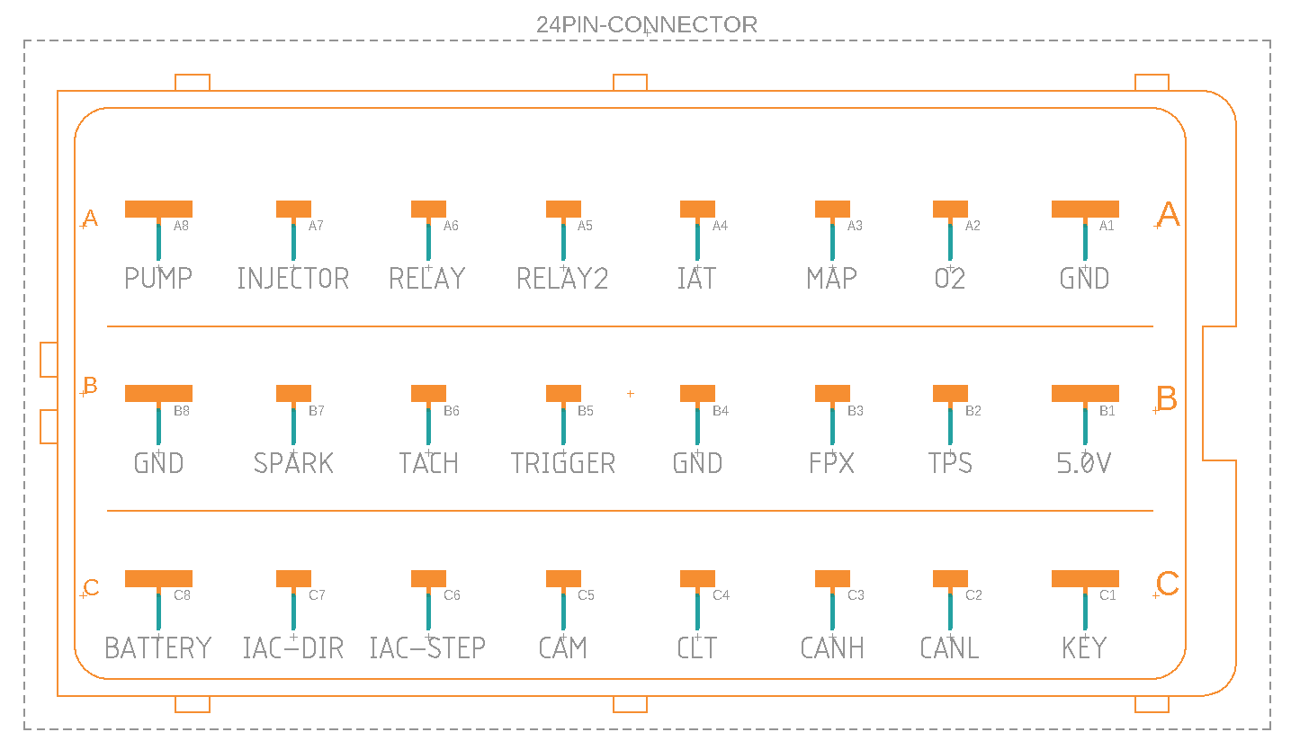
Connector Pinout - Current version v0.4.x
Here’s information that will be helpful as you’re considering an installation on your engine.
Pins may (and probably will) change, but overall functionality outlined here will remain the same. I’ll update if and when any changes occur though.
>> Pin Descriptions
I’m grouping and ordering this list in a way that I believe will flow while reading.
Power and Ground Pins
-
Pin C8: Battery (Positive) / Power
This pin serves as constant main power. Connect directly to your positive battery terminal (with a 1A fuse). See note “Overvoltage and Transient Protection on Pin C8” below. -
Pin B8: Battery (Negative) / Main Ground
This pin serves as main ground. Connect directly to your negative battery terminal. -
Pin A1: Sensor Ground
Dedicated return path for sensors. Do not attach to anything except directly to analog sensors. -
Pin B4: Trigger Ground
Dedicated return path for trigger inputs. Do not attach to anything except directly to trigger sources. -
Pin B1: 5v 3A (Out)
This pin provides power to sensors. The 3A capacity is overkill, as it’s intended to provide power to expansion modules as well at a later time. -
Pin C1: Key Switch (Ignition Switch)
Used if you’d like the ECU to enter a low-power state after shutdown. Allows the ECU to take advantage of the internal real time clock, which allows fast connection to the network and Airtune after key-on.
Digital Outputs
-
Pin A8 Fuel Pump (PWM)
Allows low-output charging systems to support standard 12V automotive fuel pumps, which are affordable and readily available, but also robust and reliable.
.
With PWM enabled, fuel pressure can be set by the user at a target value without the use of an external mechanical pressure regulator. This type of fuel pump is typically rated to draw approximately 5A which blows right through available power supply on many small engines. However, using PWM regulation we’ve seen this power requirement reduced to as low as 1.25A @ a stable 43psi. -
Pin A7 Fuel Injector
This is our single injector channel. Has same internal circuitry and capabilities as A8. Although A7 is already PWM capable, support for “peak-and-hold” injector control methods will come in a later software update.
Note: See “Transient Protection on PWM Pins” below.
-
Pin A6 Fuel Relay
Fuel relay control. Allows the ECU to kill the fuel pump and injector when switched off, regardless of pin A8 or pin A7 output states. During normal operation the fuel relay is managed by the RA2E1 processor. However, the ESP32 has the ability to override the RA and kill fuel if it detects a problem. This redundancy is for safety.
SAFETY WARNING: DO NOT bypass the automatic fuel relay functionality for any reason. Power connections for the fuel pump and injector should always be behind this relay so the ECU can cut fuel if necessary. This plays a critical role in safety, working alongside additional methods of transient and overvoltage protection.
-
Pin A5 Accessory Relay
Additional 12V relay control pin. Available to be used at your discretion depending on your needs (e.g. radiator fan, etc).
Note: Pins A8, A7, A6, and A5 are all low-side switching outputs. This means they act as a switch on the ground side of the load.
-
Pin B7 Spark (Ignition Channel)
Gate driver output. Currently being tested for use with LS2-style ignition coils. -
Pin B6 Precision Tachometer / 0° Reference
Intended for future use with I/O expansion modules. -
Pin C7 IAC Direction
Idle control valve direction logic for external driver. -
Pin C6 IAC Step
Idle control valve step logic for external driver. -
Pin C3 CAN Bus High
Intended for future use with I/O expansion modules. -
Pin C2 CAN Bus Low
Intended for future use with I/O expansion modules.
Trigger Pins (Digital Inputs)
-
Pin B5 Crankshaft Position Trigger
Relied on to determine crankshaft speed, accurate to ±1RPM. As well as to infer crankshaft position, serving as reference for all injection and ignition events. -
Pin C5 Camshaft Position Trigger
Relied on for phase detection on four-stroke engines when careful injector timing relative to intake valve opening is necessary. Any electrically compatible source of signal indicating phase can be used, not just cam sensors.
Note: Pins B5 and C5 can tolerate high voltage trigger sources. Pulses of up to 250V have been tested successfully. This is very useful because it allows for triggering directly off of magneto kill wires with no extra external converters, keeping costs down and installation simple.
Despite tolerating much higher voltages, keep in mind that the logic-high threshold is set at approximately 2.75V to 3V on both trigger channels. If your source of signal has a DC bias (like I’ve seen on Kohler engines recently), you may need to add an appropriately rated bipolar capacitor inline with the input to block that DC component.
Sensor Pins (Analog Inputs)
All sensor pins are electrical 0-5V range, with rail-to-rail protection.
-
Pin A4 IAT Sensor
Intake Air Temperature. Pin has an internal pull-up for use with NTC thermistor-based sensors. -
Pin A3 MAP Sensor
Manifold Absolute Pressure. Currently only 1-Bar MAP sensors are supported in software. This isn’t a hardware limitation, scaling will be added in a later software update. -
Pin A2 O2 Sensor
Oxygen sensor. Accepts standard 0-1V narrowband sensors by default, or the use of a 0-5V external wideband O2 controller. The O2 input mode is set in Airtune. -
Pin B3 FPX Sensor
Fuel pressure sensor. A sensor with working range of 0-100PSI and minimum failure tolerance of at least 150psi is recommended. Required for PWM fuel regulation. -
Pin B2 TPS Sensor
Throttle Position Sensor (Potentiometer-based) -
Pin C4 CLT Sensor
Coolant or Cylinder Temperature. Pin has an internal pull-up for use with NTC thermistor-based sensors.
Note: Overvoltage and Transient Protection on Pin C8 (Battery / Main Power)
Small engines very often have crude and very poorly regulated charging systems, so we need to make sure the ECU can tolerate voltages outside of normal 12V range on Pin C8.
-
30V Maximum Voltage on C8 (Failing Regulator-Rectifier Protection)
Regulator-rectifier units on small engines generally aren’t the best quality. When one fails they’re capable of driving stator level overvoltages into the battery well above normal 13.5V to 14.5V range. Sometimes into the low 20’s of volts or higher.
.
To help prevent damage to the ECU from a failing charging system, all components exposed to Pin C8 are selected with high voltage ratings and are (by their nature) able to handle unregulated DC output from a failing regulator while still allowing the ECU to operate without damage. To keep extreme overvoltages from approaching the maximum rating of those edge components, a 30V maximum threshold is imposed by an internal active clamp to give those components healthy margin. If Pin C8 experiences sustained voltages higher than ~29.95V, the clamp will begin conducting enough current to blow the upstream 1A fuse and kill the engine. This process occurs over a few milliseconds. -
Response to Inductive Transients
Relays kicking off will not cause ECU resets or nuisance fuse trips. Short duration transient events like this are cleaned up by a combination of the active MOSFET clamp, TVS diode and low-ESR capacitor on Pin C8. This occurs well before the fuse can blow.
-
Accidental 24V Jumpstarts
NanoEFI can safely handle jumpstarts from 24V charging systems without damage. -
Under-Voltage Lock Out
“UVLO” will is a protection measure to prevent glitching and unpredictable internal component behavior at insufficient system voltage. If while starting your engine, your battery voltage dips below 6.5V, you’ll want a higher capacity battery to avoid UVLO from engaging and resetting the ECU. -
Reverse Polarity Protection
If you hook the battery up backwards, the ECU will not be damaged. However, the 1A fuse will need to be replaced. In this case the blown fuse is to alert the user, rather than to protect the device.
Note: Transient Protection on PWM Pins A7 and A8
Physics is interesting, and rapidly switching a decent amount of current though a pretty big inductor can (and will) produce some pretty wild effects that will easily destroy things if not mitigated.
-
Pump Protection Diode
An anti-parallel (often called “flyback” or “freewheeling”) diode is recommended directly across the terminals of your fuel pump, as close as possible to the pump itself preferably across the terminals. This is our first layer of defense. It’s simple and effective, but not perfect as its external to the ECU and installation instructions aren’t always followed. -
Active Freeweeling (Inductive Flyback Protection)
If the pump diode is broken or missing, voltages can get nasty quickly. To deal with this and have a strong layer of internal protection on the board, the PWM channels (Pins A7 and A8) are each arranged with identical twin MOSFETs. The first FET is responsible for switching the load as you’d expect, while the second “freewheeling” FET provides an active low-impedance path for the energy stored in the pump’s windings to safely return back to the battery where it wants to go. The ECU can operate normally in this condition, but will throw an alert at you.
Note: These same principles apply to injectors run in “peak-and-hold” mode. However, a diode is not necessary on injectors run in saturation mode.
-
Power Disengage (Fuel Relay)
In addition to safely cutting fuel if a serious problem is detected, the fuel relay also doubles as an electrical “breaker” that the ECU can use to protect itself in response to sustained overvoltages on A7 and A8 from an external source. Presumably from a defective component of the charging system, or injected onto the line by some other device.
Note: As mentioned above, it’s of critical importance not to disable the automatic fuel relay functionality. The ECU needs its ability disconnect upstream power to the fuel pump and injector in a sustained overvoltage event.