Hi Everyone! 
Since our last update in July, I’ve kept up the focus on building funding and the equipment necessary to support the project through BETA. Lots of ducks to get in a row, both business and personal.
As it stands, I have a couple more (outside) jobs to wrap up. Then I expect we’ll have built enough of a runway to allow up to three or four months of dedicated full-time effort working on NanoEFI. If all goes well, stays on budget (and I manage to get enough sleep in the process) we should see the first test kits become available before the end of the year. Still, lots to do before then 
At the moment we’re doing well on budget. Before I go any further, let’s give our Patreon contributors a massive THANK YOU  for their continued support. In fact, an important piece of equipment we’ll need for BETA arrived just a few days ago!
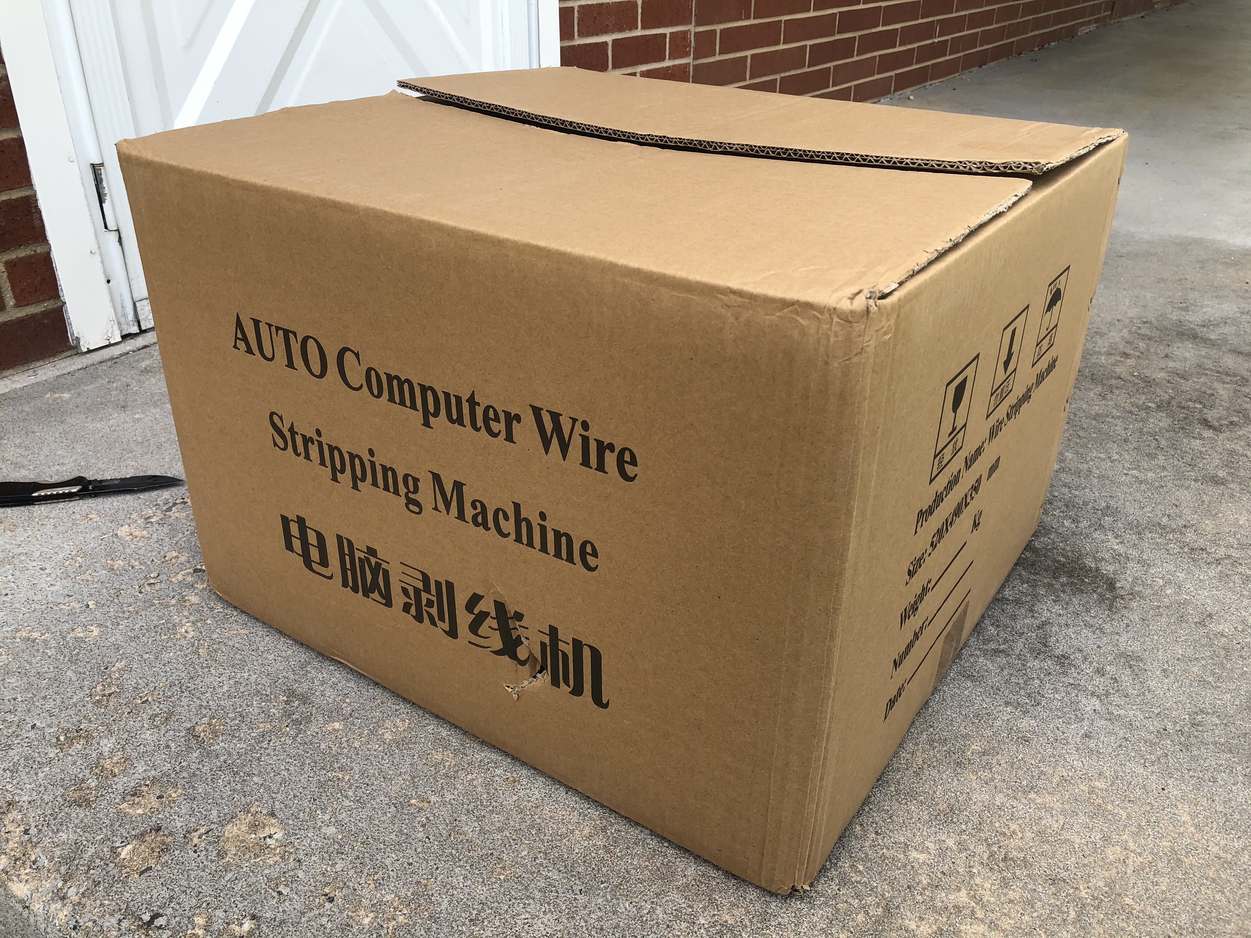
Here’s our latest score! I present to you our new automated wire cutter and stripper! 

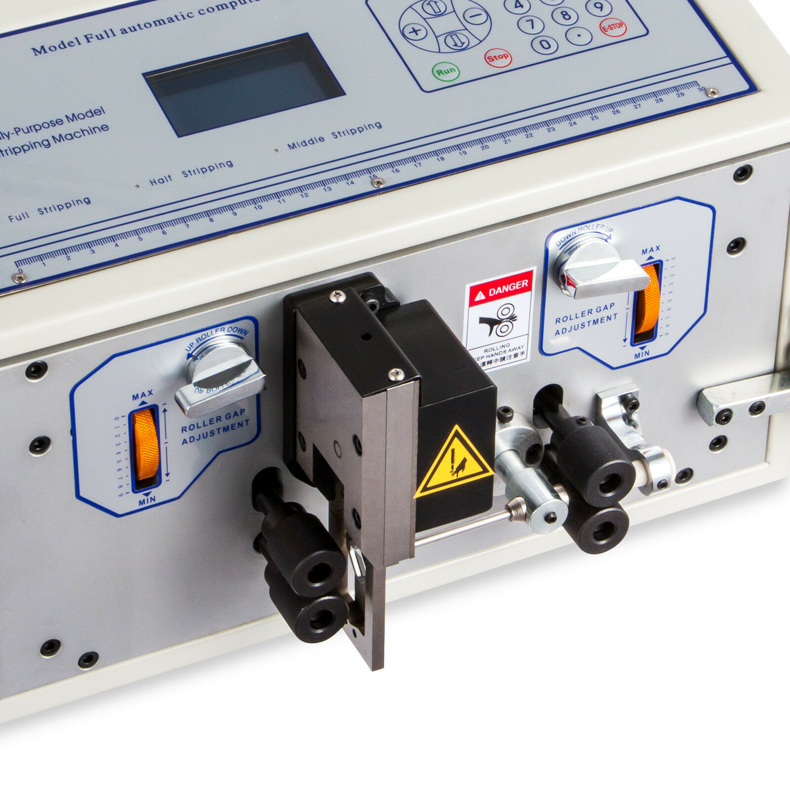
Kickin’ tires and Cuttin’ Wires 
One of my favorite past gigs was the design and production of motorsports harnesses. Mostly engine swap stuff. Here’s an example of my work 
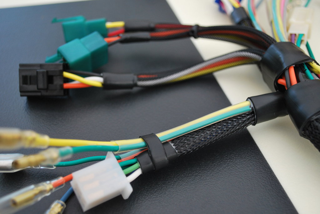
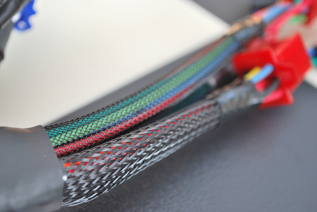
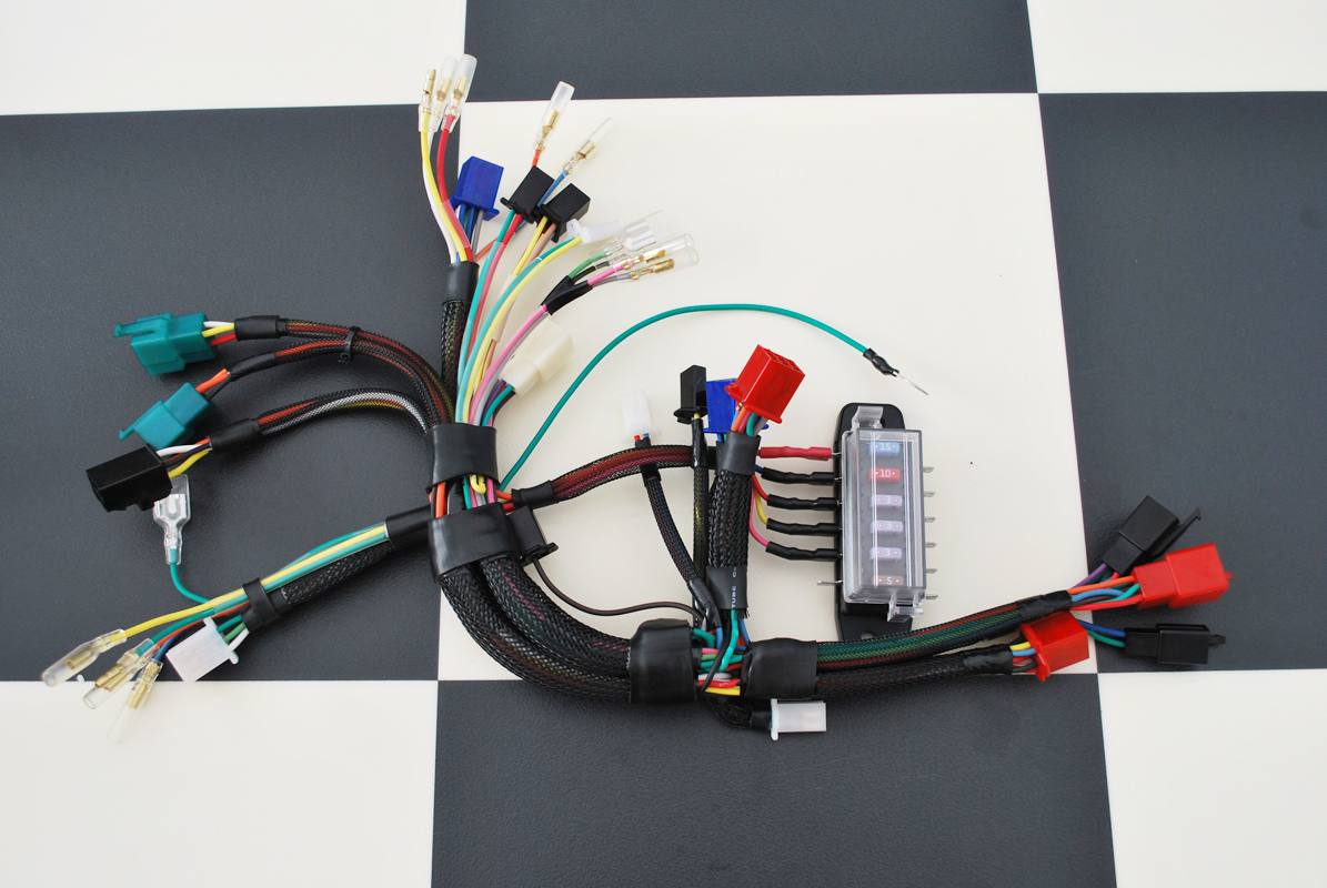
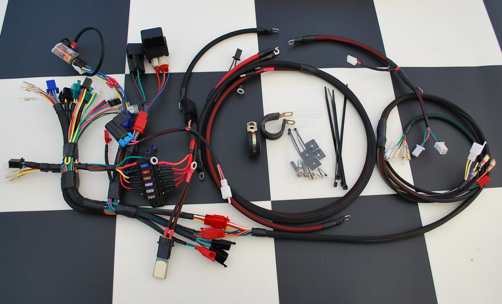
This was by hand and a lot went into doing it right. Since then I’ve still been drooling over wire processing machines, and I’m absolutely thrilled at the idea of speeding up some of the more repetitive aspects of harness building.
Running a tight ship 
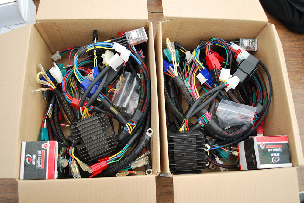
The harness is a major chunk of the cost of our EFI kits, and a risk for the project if not done right. Rather than outsourcing our harnesses starting out, I’ll be assembling harnesses myself to ensure that quality control is  , and that the cost
  isn’t inflated on this relatively small BETA run. Also, it’s important that our limited funds aren’t risked on what could very likely end up being a bad first batch if the new design is outsourced right away.
Besides, personally I find there to be a therapeutic quality to wiring and I’m looking forward to hopping back into it for while. To that end, and to make sure we get enough kits produced for you all while maintaining a sustainable level of effort for me, it’s time to introduce you to our latest hired help 


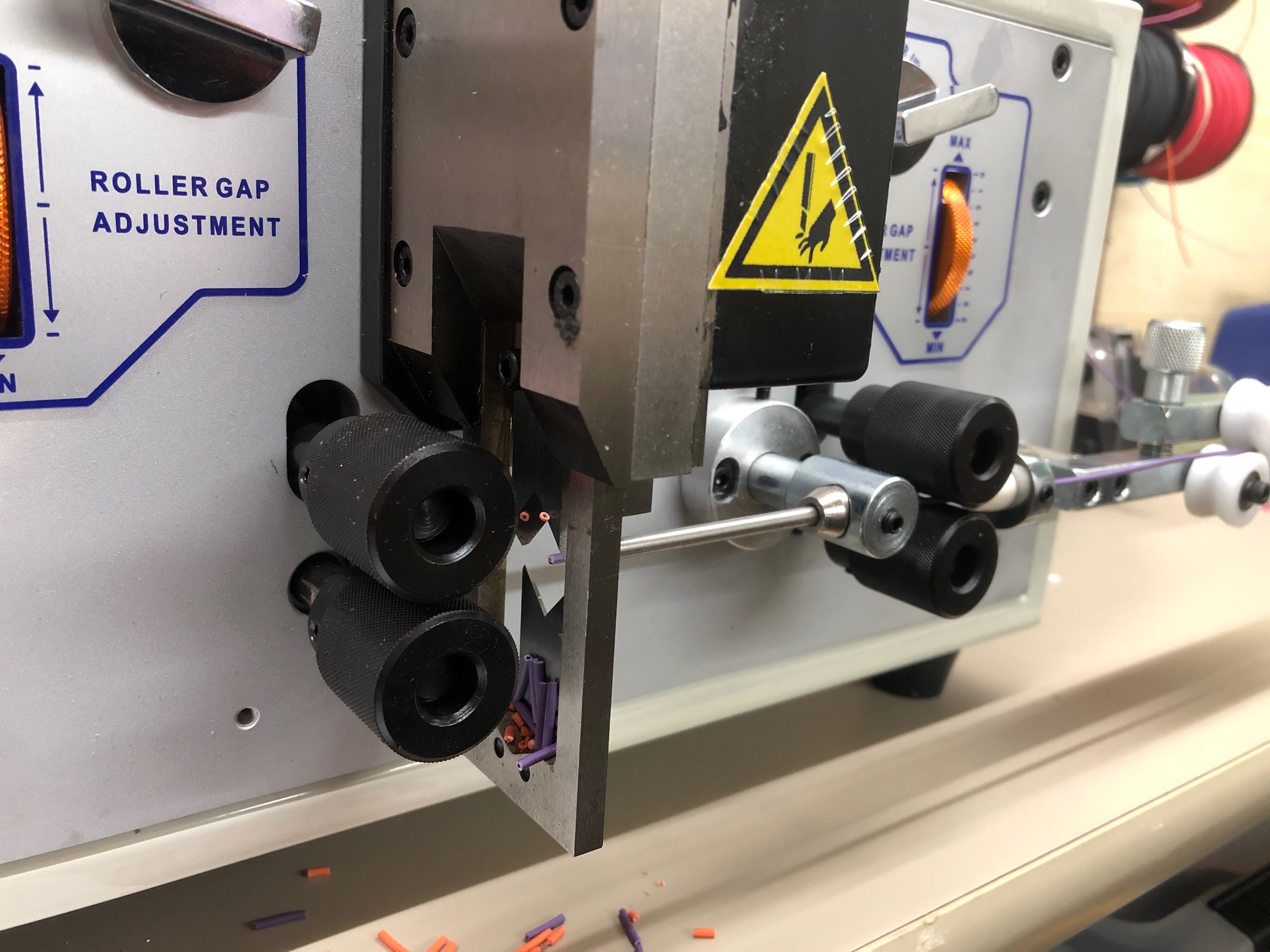
Initial Impressions
This thing shoots out wire fast! On shorter lengths, press start and you’ll have a hand full of completed pieces stripped and shot out in what seems like an instant  … Accuracy and overall consistency appears to be on point. It’s built like a tank and looks like it’ll take care of us for many years.
However, there are some concerns. The roller movements have no ease-in effect. So the wire spool often sees a lot of force abruptly, almost to the point of feeling like it’ll yank the spool off the wall before it has a chance to overcome inertia to begin rotating. I’ll need to create a buffered pulley system with some shock absorption to keep all the whirly bits happy long term.
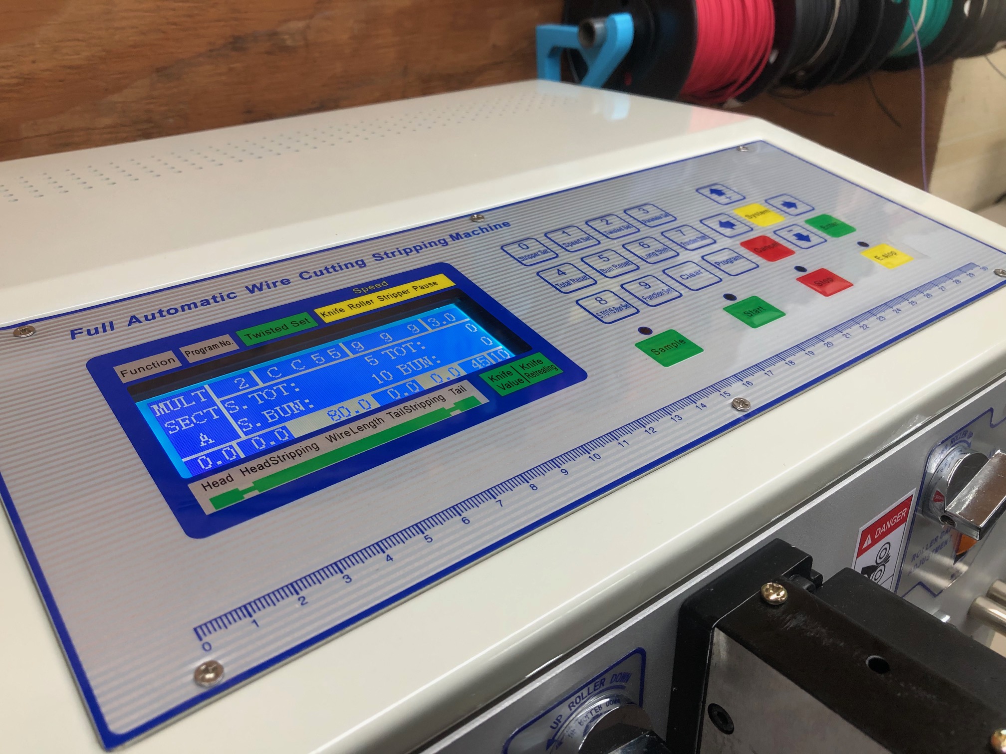
Also, the keypad+LCD interface isn’t as intuitive as it really could be. Actually… I’d say that it’s cripplingly bad. Even more so with the limited instructions provided. I’m doing well figuring out how the machine operates through a lot of trial and error. Still though (and despite the rough edges), the absolute speed and consistency is already more than making up for the learning curve.
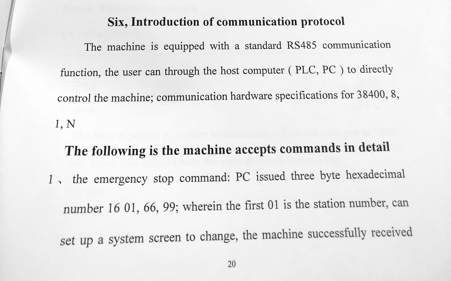
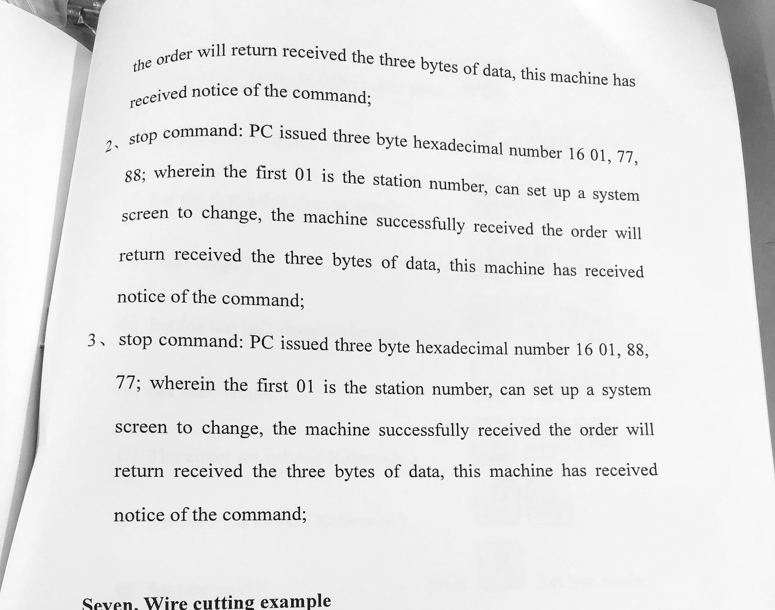
The manual did suggest there to be an RS-485 interface for issuing instructions to the machine from an external source. This is great, but only three instructions were documented: STOP, E-STOP, and what I think is START, but nothing on program entry or selection  … I’ll see about finding or reverse-engineering the rest of the list one way or another. This would go a long way to making model-specific harness variations doable. Allowing for a separate visual GUI to help take care of calculations and entering programs, well… programmatically. Very similar to Airtune or Octoprint.
I’ll have more to show soon, stay tuned. Thanks everyone!